Electromechanical generator for, and method of, converting mechanical vibrational energy into electrical energy

a technology of electrical energy and mechanical vibration, applied in the direction of generator/motor, machine/engine, electric generator control, etc., can solve the problems of inability to accurately predict the resonant frequency or optimal damping factor, inability to ensure that the practical operating conditions correspond to the theoretical ideal, and inability to optimise the actual power output for the specific application. , to achieve the effect of reducing the possibility of damage and enhancing the operating li

Active Publication Date: 2008-03-18
PERPETUUM +1
View PDF11 Cites 122 Cited by
  • Summary
  • Abstract
  • Description
  • Claims
  • Application Information

AI Technical Summary

Benefits of technology

[0013]Accordingly, there is a need to provide an electromechanical generator that accommodates the possibility that the amplitude of vibration of the sprung mass may vary with time, in an intermittent and unpredictable manner, and can accordingly have a reduced possibility of damage from unsafe amplitudes, and thereby an enhanced operating lifetime.
[0015]The present invention also aims to provide an improved electromechanical generator for converting mechanical vibrational energy into electrical energy which is adapted to prevent the amplitude of the resonator from rising above a certain threshold.
[0016]The present invention also aims to provide an improved electromechanical generator for converting mechanical vibrational energy into electrical energy which is adapted to reduce the amplitude of the resonator when the amplitude rises above a certain threshold.
[0017]The present invention also aims to provide an improved electromechanical generator for converting mechanical vibrational energy into electrical energy which includes a limiter for the vibration amplitude that does not cause any power loss from the generator below a particular or predetermined amplitude threshold, thereby avoiding or minimizing any reduction in the energy conversion efficiency of the electromechanical generator when the electromechanical generator is operating in a particular or predetermined amplitude operating range which is less than or not greater than the particular or predetermined amplitude threshold.

Problems solved by technology

While this prior disclosure produced a useful mechanism for designing a theoretical electromechanical generator, when an electromechanical generator is used in a practical application, it is not possible accurately to predict the resonant frequency or the optimal damping factor.
However, there is no guarantee that the practical operating conditions correspond to the theoretical ideal used to set up the electromechanical generator for the specific application.
However, it is very unlikely that the actual power output is optimised for the specific application.
Consequently, the electromechanical generator would not operate at maximum efficiency of the conversion of mechanical vibration energy into electrical energy, and thereby into useful electrical power.
Also, the frequency of ambient vibration may change during operation.
The known electromechanical generator may not be able to operate at maximum efficiency as a result of such a change.
These variables are not all predictable from the actual conditions encountered when the electromechanical generator is put into use in the field to harvest energy from a vibrating body.
The amplitude of vibration of the sprung mass may vary with time, in an intermittent and unpredictable manner.
In particular, the electromechanical generator may, in use, be subjected to a vibration that causes the sprung mass to oscillate with excessively large amplitude (hereinafter referred to as an “unsafe” amplitude) with the result that the mass may physically impact upon the device's outer casing at the limits of its travel.
Alternatively if there is no casing, then the mass may oscillate with an excessively large amplitude that causes permanent damage or degradation to the spring by exceeding the yield stress of the spring material.
In either case, it may be expected that this impacting or yielding would reduce the operating lifetime of the electromechanical generator to an unacceptable degree.
However, such a “mechanical stop” would be subject to wear and would not completely eliminate the extra stress to which the spring would be subjected on impact.
However if such a device is situated in an environment where the driving vibration becomes higher in magnitude than expected, then the amplitude of the resonator may become larger than the that designed or accommodated for.
This amplitude may cause the resonating mass to impact on the device casing and potentially lead to permanent device damage after prolonged exposure.

Method used


Image

  • Electromechanical generator for, and method of, converting mechanical vibrational energy into electrical energy
  • Electromechanical generator for, and method of, converting mechanical vibrational energy into electrical energy
  • Electromechanical generator for, and method of, converting mechanical vibrational energy into electrical energy

Examples


first embodiment

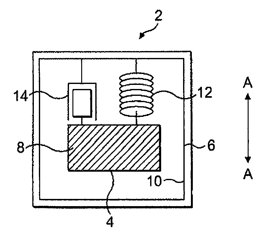
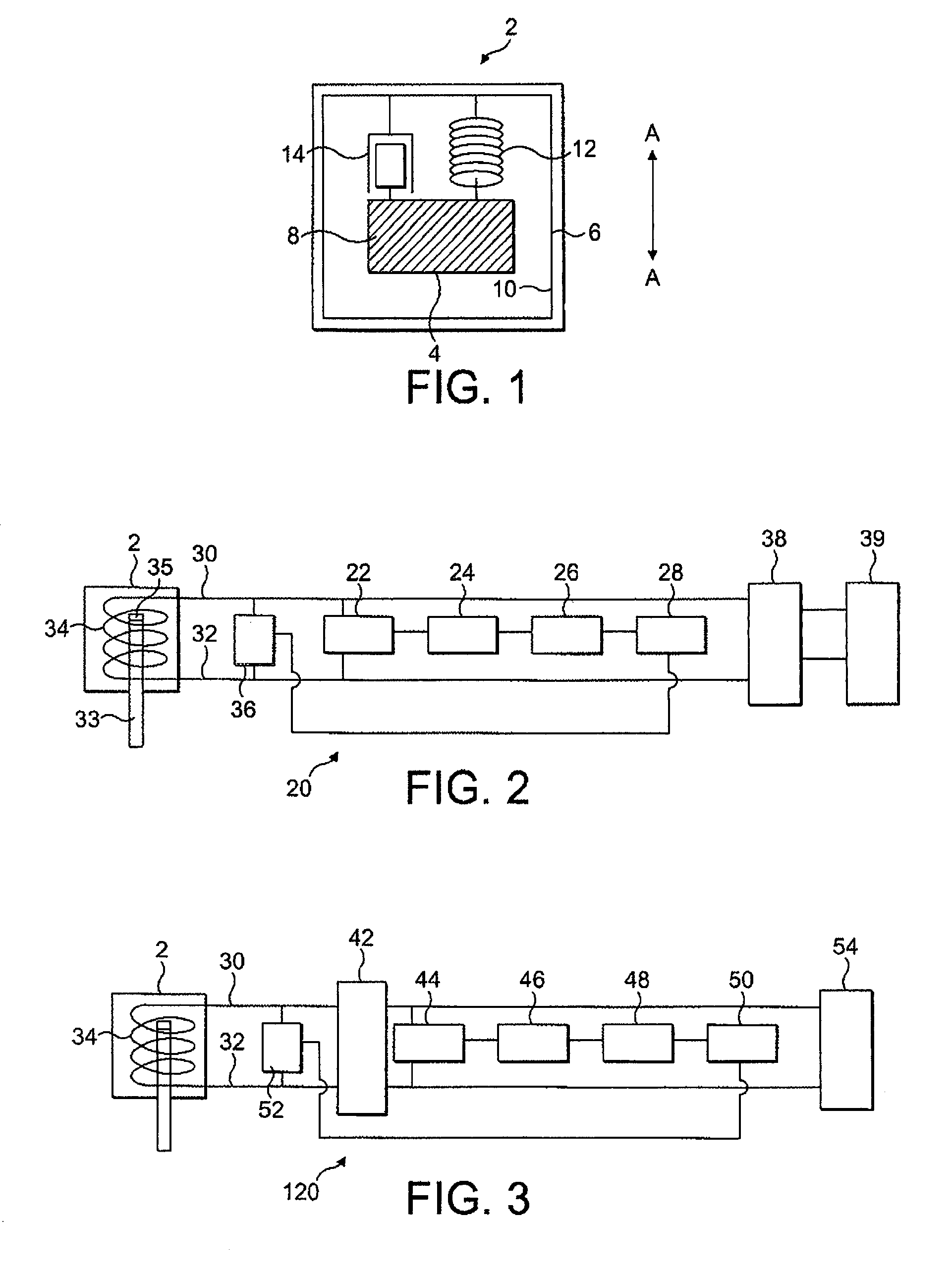
[0058]FIG. 2 is a schematic block diagram of an electromechanical generator 20 in accordance with the present invention.

[0059]The electromechanical generator 20 comprises the electromechanical device 2 for converting mechanical vibrational energy into electrical energy as described above with reference to FIG. 1. A detector 22 is connected to the electrical output of the electromechanical device 2, in this embodiment comprising the terminals 30, 32 of at least one coil 34, the coil 34 mounted relative to a cantilever beam 33 carrying at least one magnet 35. The detector 22 is adapted to detect the output voltage (Vout) and the output current (Iout) produced by the electromechanical device 2. An EMF calculator 24 is connected to the detector 22 and is adapted to calculate a quantity representing the output EMF of the transduction element according to the following expression:

EMF=Vout+(Iout*Rtrans)

where Rtrans is the internal impedance of the transduction element (e.g. the coil) of th...

second embodiment

[0065]FIG. 3 is a schematic block diagram of an electromechanical generator 120 in accordance with the present invention.

[0066]The second embodiment is modified as compared to the first embodiment by detecting rectified DC voltage and current from the AC / DC rectifier which is connected to the electrical output of the electromechanical device 2, in this embodiment the output terminals of the coil. Accordingly, in the second embodiment the electromechanical generator 120 comprises the electromechanical device 2 for converting mechanical vibrational energy into electrical energy as described above with reference to FIG. 1. An AC / DC rectifier 42 is connected to the output terminals 30, 32 of the coil 34. A detector 44 is connected to the electrical output of the rectifier 42 and is adapted to detect the output DC voltage and the output DC current produced by the rectifier 42. An EMF calculator 46 is connected to the detector 44 and is adapted to calculate a quantity representing the coi...

third embodiment

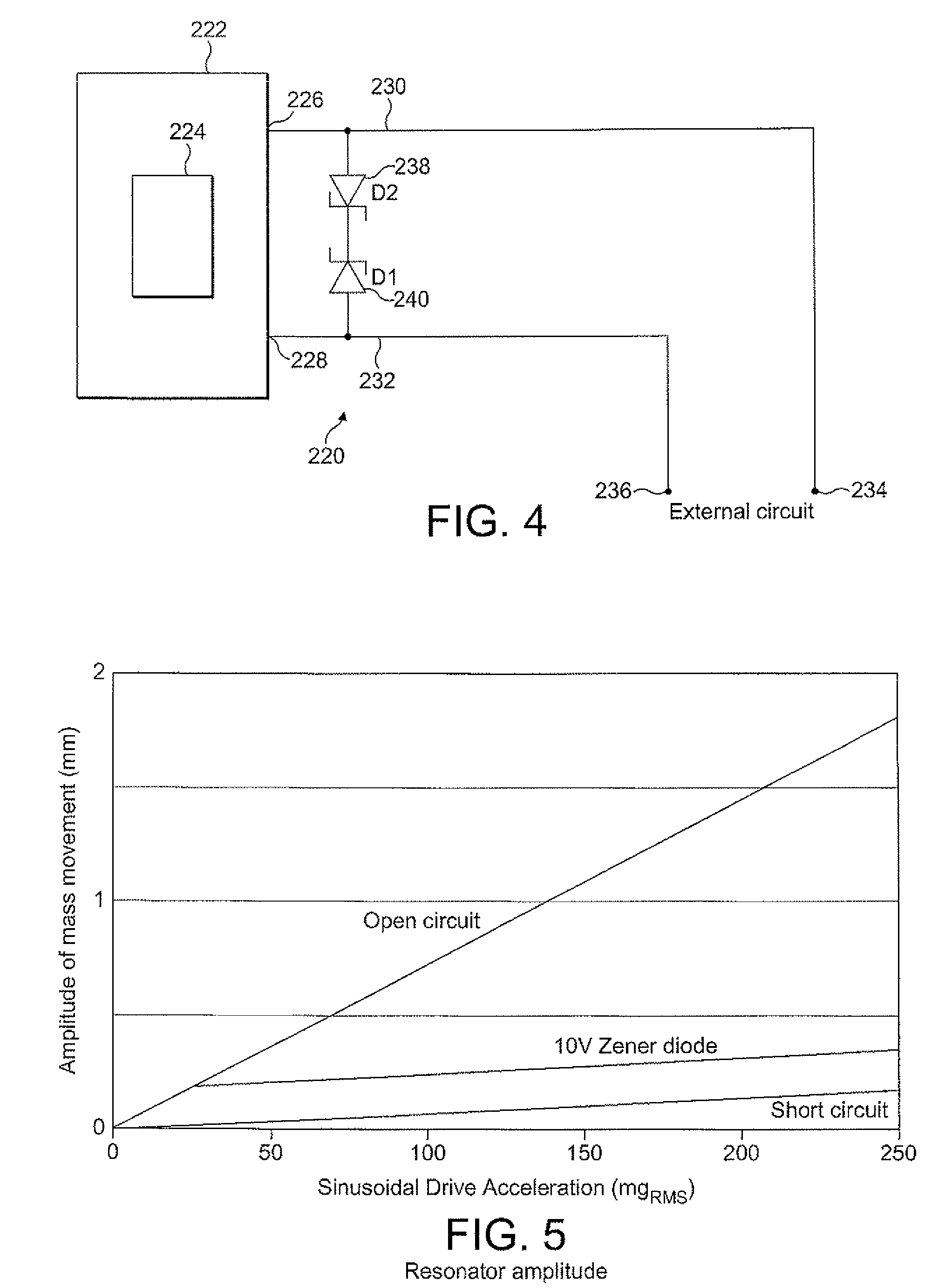
[0072]an electromechanical generator in accordance with the present invention is shown in FIG. 4. The electromechanical generator 220 comprises an electromechanical device 222 having a mass-spring arrangement 224 in the form, for example, of the mass-spring arrangements of any of FIGS. 1 to 3 in which a vibratable mass is adapted to resonate with an oscillation amplitude at a natural frequency. The electromechanical device 222 has an electrical output, which in this embodiment is comprised of two output terminals 226, 228, each having a respective electrical lead 230, 232 connected thereto. In use, the electrical lead 230, 232 are connected by respective connectors 234, 236 to an external electrical circuit to be electrically driven by the electromechanical generator 220.

[0073]Two voltage regulators 238, 240 are connected in parallel across the electrical leads 230, 232. Each voltage regulator 238, 240 is adapted to permit current flow therethrough, at a low impedance, in a respecti...


PUM


Abstract

An electromechanical generator comprising an electromechanical device for converting mechanical vibrational energy into electrical energy, the electromechanical device having a vibratable mass adapted to resonate with an oscillation amplitude at a frequency and a regulator for regulating the oscillation amplitude to a value not greater than a maximum threshold.

Description

BACKGROUND TO THE INVENTION[0001]The present invention relates to an electromechanical generator for converting mechanical vibrational energy into electrical energy and to a method of converting mechanical vibrational energy into electrical energy. In particular, the present invention relates to such a device which is a miniature generator capable of converting ambient vibration energy into electrical energy for use, for example, in powering intelligent sensor systems. Such a system can be used in many areas where there is an economical or operational advantage in the elimination of power cables or batteries.DESCRIPTION OF THE PRIOR ART[0002]There is currently an increasing level of research activity in the area of alternative power sources for micro electrical mechanical systems (MEMS) devices, such devices being described in the art as being used for ‘energy harvesting’ and as ‘parasitic power sources’. Such power sources are currently being investigated for powering wireless sens...

Claims


Application Information

Patent Timeline
Patent Type & Authority Patents(United States)
IPC IPC(8): H02P9/04H02N1/00
CPCF03G7/08H02P9/006H02K7/1892
Inventor ROBERTS, STEPHENCHINI, BEHROOZ
Owner PERPETUUM
Why Eureka
Try Eureka