Method of embedding tooling control data within mechanical fixture design to enable programmable logic control verification simulation

a technology of programmable logic and mechanical fixture design, applied in the field of programmable logic controllers, can solve the problems of limited scope of current modeling technologies, limited scope of manufacturing process, and high cost, and achieve the effect of reducing the potential for mechanical design assumptions, increasing the accuracy of virtual programmable logic control verification simulations, and reducing the time it takes

Inactive Publication Date: 2008-03-18
FORD MOTOR CO
View PDF45 Cites 13 Cited by
  • Summary
  • Abstract
  • Description
  • Claims
  • Application Information

AI Technical Summary

Benefits of technology

[0009]One advantage of the present invention is that a method of embedding tooling control data within a mechanical fixture design to enable programmable logic control verification simulation is provided for use in building a manufacturing line to manufacture a motor vehicle. Another advantage of the present invention is that the method reduces the amount of time it takes to conduct virtual programmable logic control verification simulations. Yet another advantage of the present invention is that the method increases the accuracy of virtual programmable logic control verification simulations. Still another advantage of the present invention is that the method lowers the potential for loosing mechanical design assumptions related to control system design through a body shop fixture tooling design process, such as naming conventions, tooling sequence description, bill of materials for control and mechanical items, etc. A further advantage of the present invention is that the method supports effective control logic system design simulation approach by automatically producing tooling visualization data that describes the allowable tooling behavior, that is used by a virtual programmable logic controller. Yet a further advantage of the present invention is that the method exports mechanical fixture data such that all the relationships are maintained between tooling items that move (e.g., clamps, dumps, shuttles, etc.), the sequence (order) in which it is estimated that the tools need to move within the manufacturing environment, items that are structural and do not move but take up space on the floor and need to be accounted for in the virtual PLC simulation to test for possible collisions with moving tooling, and control items such as sensors, switches, actuators, which sense the position of parts and or tooling. Still a further advantage of the present invention is that the method exports fabrication information from a mechanical fixture design to support a floor build of tooling.

Problems solved by technology

Current modeling technologies, such as Robcad from Tecnomatix and Igrip from Delmia, for the manufacturing process are limited in scope to a workcell level, due to how these type of technologies represent and manipulate three dimensional data and tool motions.
This scope limitation is due to the manner in which tooling geometry is defined and the manner in which tool motions are described and displayed to a user.
The tooling and robotic motions are also microprocessor intensive in that the articulations and movements are described through the use of complex kinematic equations and solvers.
Presently, there is no modeling mechanism to verify that the planned interactions between linked workcells is indeed feasible until the manufacturing line is actually fabricated and assembled on a floor of a manufacturing plant.

Method used


Image

  • Method of embedding tooling control data within mechanical fixture design to enable programmable logic control verification simulation
  • Method of embedding tooling control data within mechanical fixture design to enable programmable logic control verification simulation
  • Method of embedding tooling control data within mechanical fixture design to enable programmable logic control verification simulation

Examples


Embodiment Construction

)

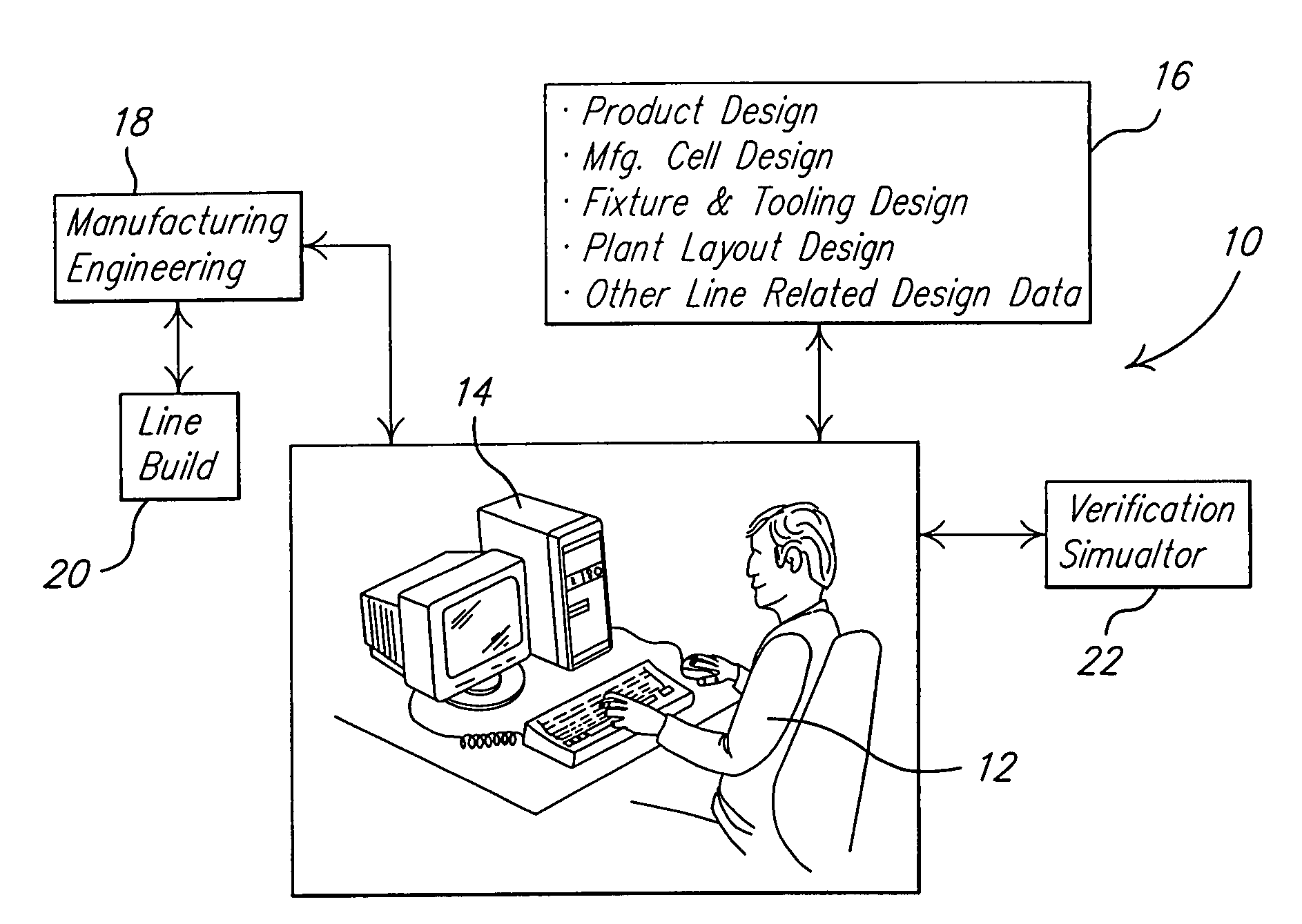
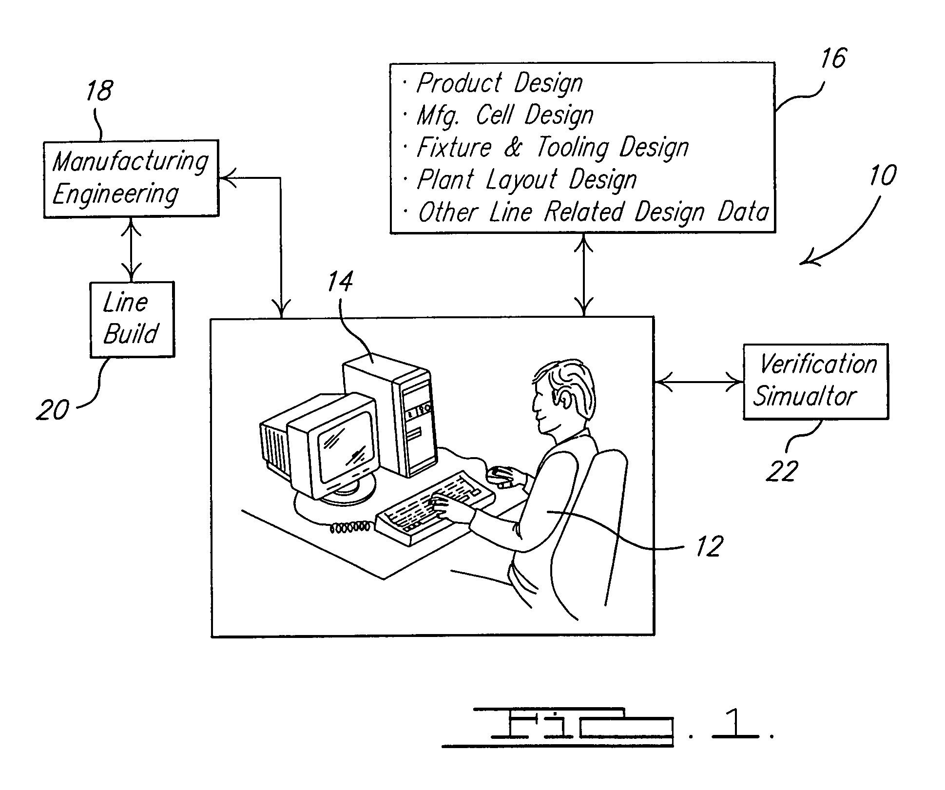
[0013]Referring to the drawings and in particular FIG. 1, one embodiment of a system 10, according to the present invention, for embedding tooling control data within a mechanical fixture design to enable programmable logic control verification simulation is illustrated. In the present invention, an operator 12 uses the system 10 to perform programmable logic control verification simulation. The system 12 includes a computer 14 to send and receive information to and from a design engineering source 16 via an electronic link. The design engineering source 16 includes a product design system, work cell design system, manufacturing cell design system, mechanical fixture and tooling design system, controls design system, plant layout design system, and other manufacturing line related design systems to provide engineering data for standard components, tools, fixture models, and robots to interact with the fixture models. These design systems have the ability to read and write in a neut...


PUM


Abstract

A method is provided of embedding tooling control data within a mechanical fixture design to enable programmable logic control verification simulation. The method includes the steps of constructing at least one of a mechanical fixture design, a workcell design, and a controls design. The method also includes the steps of executing a virtual programmable logic control (VPLC) simulation with a VPLC verification simulator to verify the at least one of the mechanical fixture design, the workcell design, and the controls design.

Description

BACKGROUND OF THE INVENTION[0001]1. Field of the Invention[0002]The present invention relates generally to programmable logic controllers and, more specifically, to a method of embedding tooling control data within a mechanical fixture design to enable programmable logic control verification simulation.[0003]2. Description of the Related Art[0004]It is known that programmable logic controller (PLC) code is written by controls engineers after assembly tooling designs are completed and a manufacturing process has been defined. The creation of the programmable logic controller code is mostly a manual programming task with any automation of the code generation limited to “cutting and pasting” previously written blocks of code that were applied to similar manufacturing tools. Once the programmable logic controller code is written, it is used by a tool builder to fabricate subsequent hard tools used in the manufacture and assembly of parts for motor vehicles. The programmable logic contro...

Claims


Application Information

Patent Timeline
Patent Type & Authority Patents(United States)
IPC IPC(8): G06F9/455
CPCG05B19/056G05B19/41885G05B2219/13174G05B2219/13176G05B2219/35043G05B2219/49123Y02P90/02
Inventor WALACAVAGE, JOEBAUMGARTNER, ALANKENNEDY, SCOTTGANTI, SHANKERNEWMAN, ERIC
Owner FORD MOTOR CO
Why Eureka
Try Eureka