Method of protecting a capacitor

a technology of capacitors and membranes, applied in the direction of variable capacitors, fixed capacitor details, fixed capacitors, etc., can solve the problems of inadequate moisture protection, deformation and failure of many capacitive elements, and add significantly to the cost, size and weight of these conventional capacitors, and achieve less expensive or unsealed, low gas, and light weight

Active Publication Date: 2008-04-01
HAMILTON SUNDSTRAND CORP
View PDF24 Cites 10 Cited by
  • Summary
  • Abstract
  • Description
  • Claims
  • Application Information

AI Technical Summary

Benefits of technology

[0008]The electric device according to the present invention provides an electric element, such as a wound film capacitor, with power input and output leads. The electric element includes a coating layer of poly-para-xylylene, generically known as parylene. The coating layer provides moisture resistance and low gas and moisture permeability to protect the electric element from short and long-term moisture degradation effects. The coating layer is between about 0.0003 inches and about 0.3 inches thick.
[0009]A known case layer is located adjacent to the coating layer. The case layer is a metal, epoxy-based, silicone-based, or polymer material that encapsulates the coating layer and the electric element to protect the coating layer and electric element from physical damage. Since the coating layer provides gas and moisture resistance, a thinner, lighter, less expensive or unsealed case layer may be utilized than would be used in prior art electric devices without a coating layer.
[0010]The electric device of the present invention therefore provides a compact, light weight, and inexpensive capacitor that resists moisture infiltration.

Problems solved by technology

Many capacitive elements, such as those constructed of wound elements of metallized polymer film, will degrade and fail due to corrosion or other moisture-related processes if exposed to high levels of moisture or low levels of moisture for significant periods of time.
However, the plastic and metal cases used for this purpose may exhibit inadequate moisture protection and add significantly to the cost, size and weight of these conventional capacitors.
These designs, coatings, and related processes, however, may interfere with cooling airflow, repair and maintenance activity, and other operational requirements.
Additionally, the designs and coating may increase the cost, size, and / or weight of the electronic unit.

Method used


Image

  • Method of protecting a capacitor
  • Method of protecting a capacitor
  • Method of protecting a capacitor

Examples


Embodiment Construction

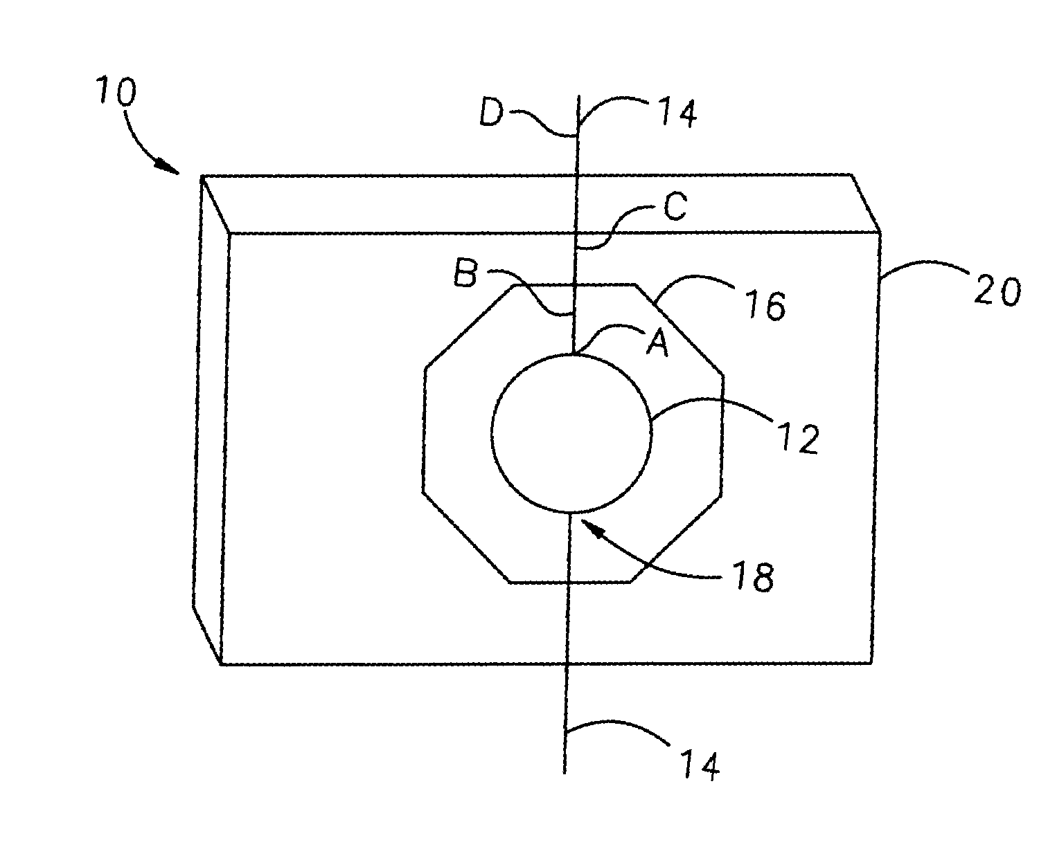
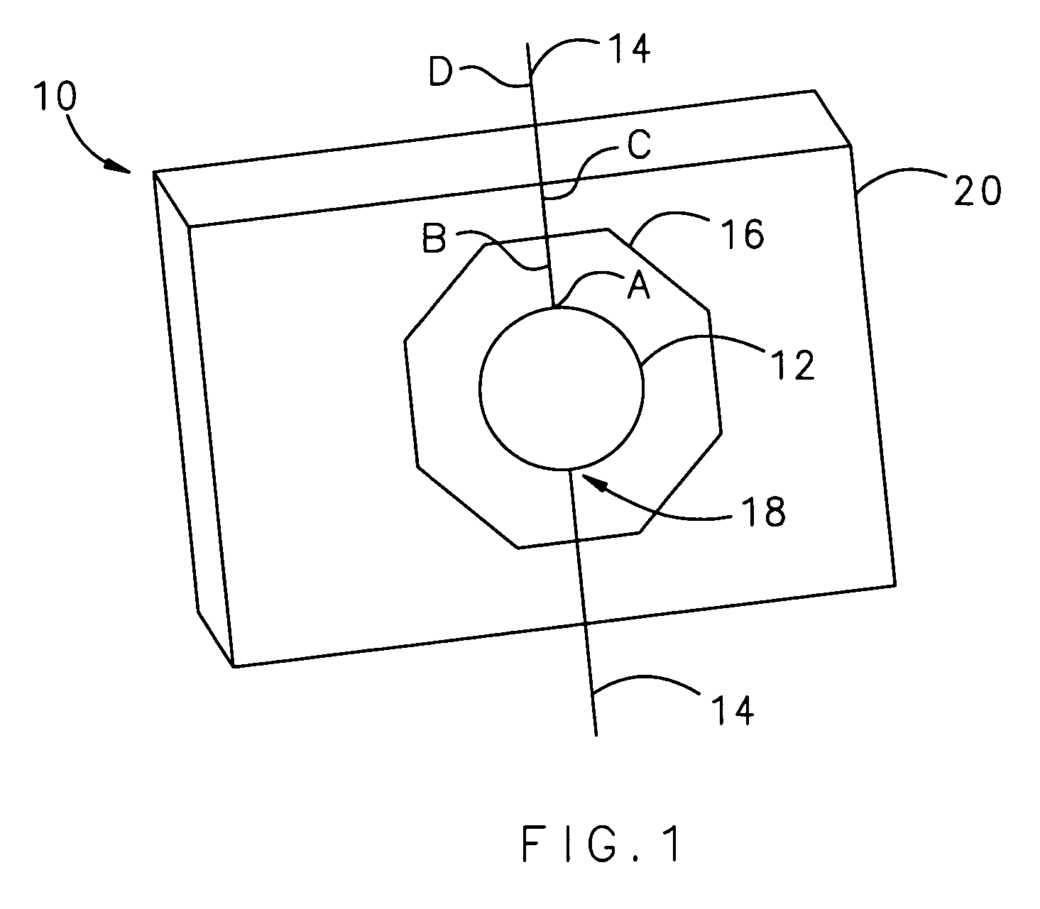
[0014]FIG. 1 illustrates a schematic cross-sectional view of an electric device 10. The electric device 10 includes an electric element 12, preferably a wound film capacitor, with electric leads 14 for power input and output. The electric leads each include a first portion A coupled to the electric element 12, a second portion B, third portion C, and fourth portion D that extends from the electric element 12. A coating layer 16 is deposited adjacent to the electric element 12.

[0015]The coating layer 16 is a polymer, preferably poly-para-xylylene. Poly-para-xylylene is also known generically as “Parylene” which is a polymer series developed by Union Carbide. The term “Parylene” describes vapor deposited poly-para-xylylene polymers without referring to any particular chemical formulas or manufacturers for any particular polymers of this chemical family. Parylene generally exhibits fine moisture resistance and low gas and moisture permeability and thus provides a protective barrier for...


PUM

PropertyMeasurementUnit
thickaaaaaaaaaa
thickaaaaaaaaaa
thicknessaaaaaaaaaa

Abstract

An electric device includes an electric element, such as a wound film capacitor, with power input and output leads. The electric element includes a coating layer of parylene that provides moisture resistance and low gas and moisture permeability to protect the electric element from short and long term moisture degradation effects. A known case layer is located adjacent to the coating layer. The case layer is a metal, epoxy-based, silicone-based, or polymer material that encapsulates the coating layer and the electric element to protect the coating layer and electric element from physical damage.

Description

BACKGROUND OF THE INVENTION[0001]This invention relates to moisture sealing of electronic devices and, more particularly, to coating a capacitor element with a moisture resistant material layer.[0002]Aircraft and other equipment utilize capacitors in avionics, power converters, electric / electronic motor controllers and other applications. Capacitors are used for electrical energy storage, waveform shaping, electromagnetic interference, lightning protection and other similar functions. Increased use of electronic devices in avionics and other applications, such as in electronic motor controllers in place of previously used hydraulic, pneumatic, or other power sources, increases the number and size of capacitors used in these applications.[0003]Aircraft and other equipment that are exposed to ambient unprotected weather conditions and / or to high humidity environments in normal operation or storage require that exposure to moisture not affect the operation, life, maintenance cost, or r...

Claims


Application Information

Patent Timeline
Patent Type & Authority Patents(United States)
IPC IPC(8): H01G7/00
CPCH01G2/103H01G4/32Y10T29/4913Y10T29/49002Y10T29/49169Y10T29/43Y10T29/49146
Inventor SCHNETKER, TED R.
Owner HAMILTON SUNDSTRAND CORP
Why Eureka
Try Eureka