Vacuum measuring gauge

a vacuum measuring and gauge technology, applied in the direction of fluid pressure measurement, instruments, discharge tube/lamp details, etc., can solve the problems of deteriorating measuring accuracy, unsatisfactory interference with other measurements, and usually sensitive to vibration, and achieves simple and mechanically stable, high electron density in the reaction region, and easy manufacturing solutions

Inactive Publication Date: 2008-04-01
INFICON GMBH
View PDF28 Cites 22 Cited by
  • Summary
  • Abstract
  • Description
  • Claims
  • Application Information

AI Technical Summary

Benefits of technology

[0008]In a vacuum measuring gauge according to the invention a larger emitter area can be accommodated in a housing of a given size. An electrode configuration with a larger emitter area. As the emitter surface can be made large the required electron flow density at the same may be comparatively small such that moderate field strengths will usually be sufficient. This alleviates requirements on the cathode and allows for a wider choice of material and structure for the emitter surface.
[0009]In many cases relatively cheap, easy to manufacture solutions will become practical. The emitter area may be formed by an emitter layer on the surface of the housing wall or even by the wall surface itself in which case the vacuum measuring gauge is especially simple and mechanically stable.
[0010]Where the emitter area is concave and in part surrounds a reaction region containing the ion collector, the electrons emitted by the cathode will remain in the reaction region until they eventually reach the anode. They will repeatedly collide with molecules of the rarefied gas in the reaction region and thereby produce ions which can be used in the measuring process. Only a small fraction of the electrons will escape and reach the housing along a relatively short trajectory, even where no special measures, like keeping the housing at a voltage which is lower than the emitter voltage, are taken to prevent it. Even with a modest electron flow from the cathode, electron density in the reaction region will be high and a high yield of ions is assured.
[0011]The high achievable ion yield, together with the absence of side effects like desorption of gas molecules allow for extension of the measurement range to very low densities. At the same time, the required voltages are relatively small which allows the use of a rather simple and cheap control circuit with low power consumption.

Problems solved by technology

The cathode emits electromagnetic radiation which may influence measurement results in not precisely predictable ways and may lead to undesirable interference with other measurements.
It is usually sensitive to vibrations which are often unavoidable in industrial processes.
This may again lead to a deterioration of measuring accuracy and over time even to the destruction of the cathode.
The kinetic energies of the emitted electrons are distributed over a relatively wide interval which reduces efficiency and may also lead to fluctuations of the sensitivity of the gauge.
They do not as a rule cause side effects which might impact on measurement results in ways which are difficult to assess and compensate for.
The latter requirement may cause considerable strain on the material resulting in wear, e.g., due to sputtering, thereby reducing the service life of the gauge.

Method used


Image

  • Vacuum measuring gauge
  • Vacuum measuring gauge
  • Vacuum measuring gauge

Examples


Embodiment Construction

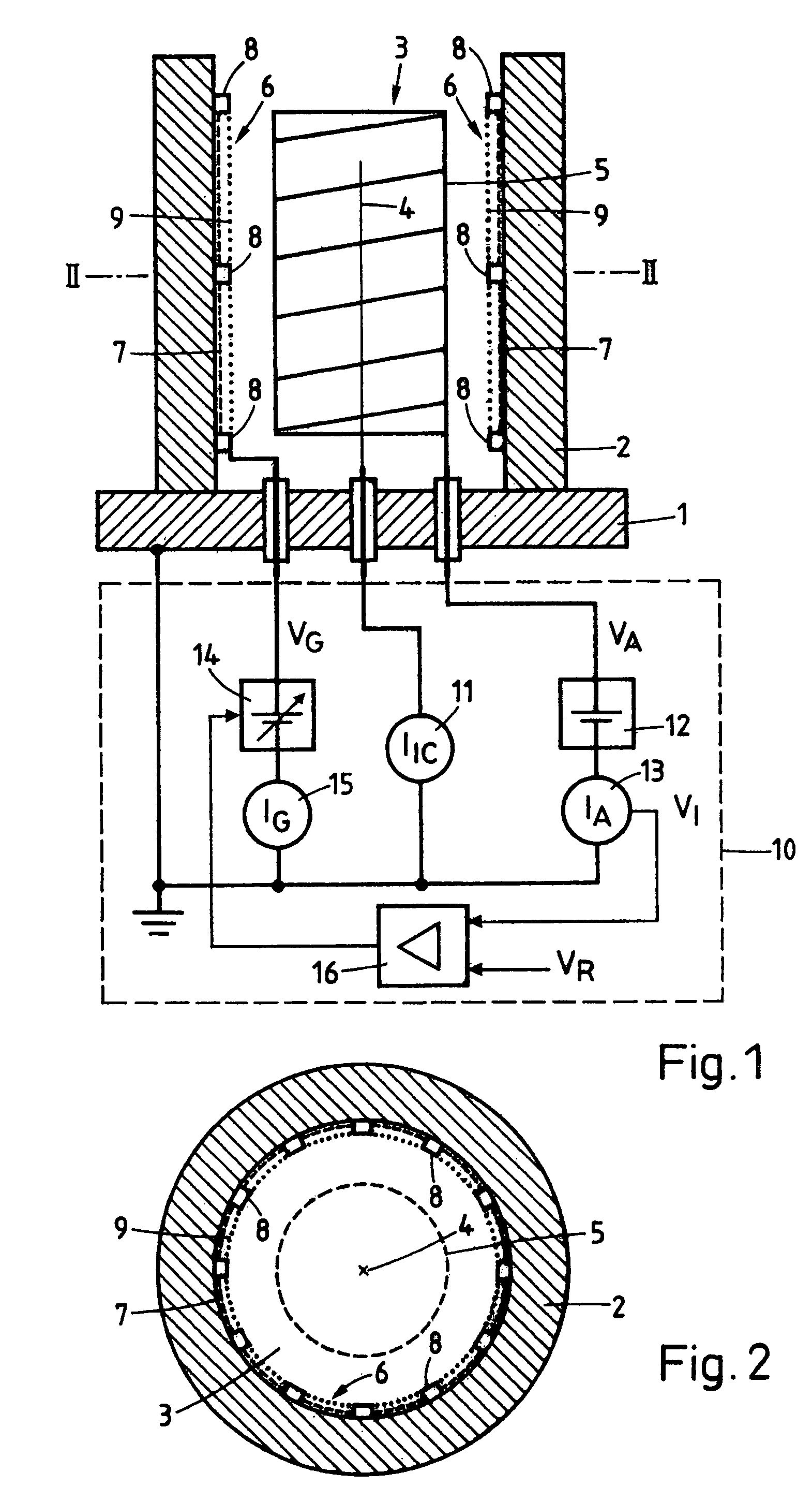
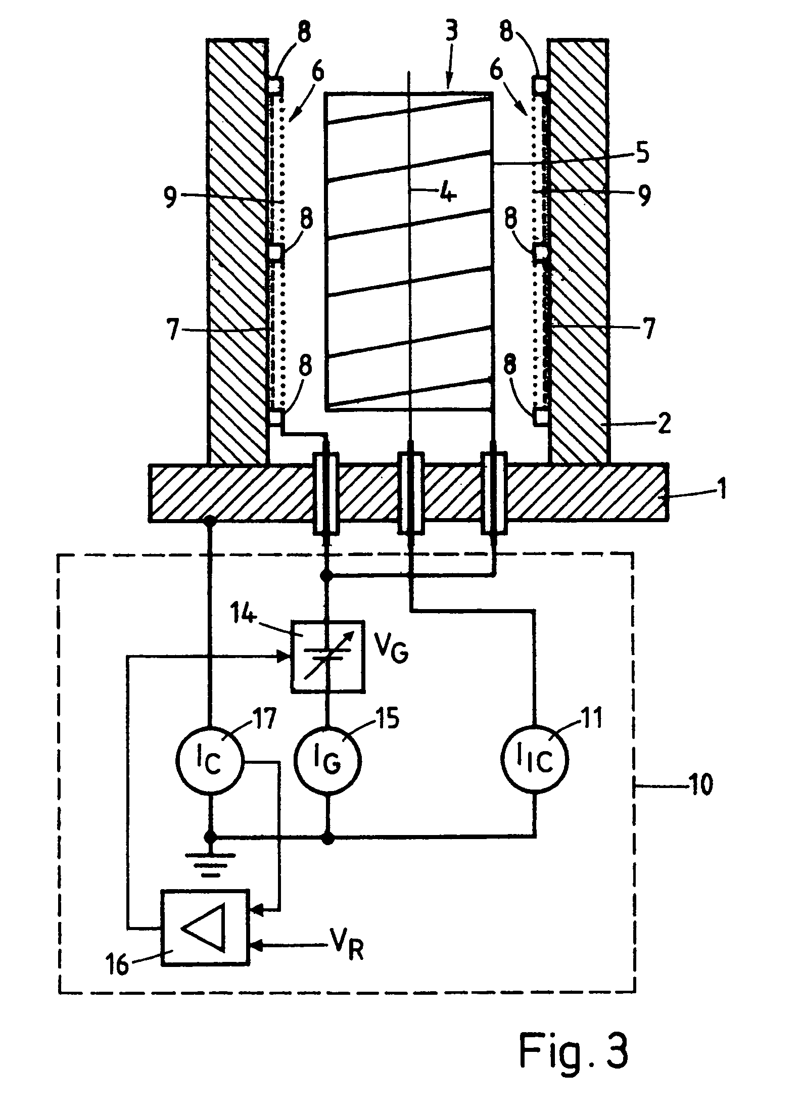
[0018]The embodiment of the vacuum measuring gauge according to the invention of FIG. 1, 2 comprises a housing with a base plate 1 and a side wall 2 mounted on the base plate 1 which laterally encloses a cylindrical reaction region 3 which is open at the top so as to be connected with a vacuum chamber where the gas pressure is to be measured. The base plate 1 and the side wall 2 together form the housing. Preferably they consist each of an electrically conductive material, in particular stainless steel or aluminium. In the axis of the reaction region 3 an ion collector 4 in the shape of a straight thin axial filament or wire is arranged which is surrounded at a distance by an essentially cylindrical grid-like anode 5, e.g. a helix-shaped wire. The ion collector 4 and the anode 5 each consist of a metal or alloy, e.g., the ion collector 4 of tungsten or stainless steel and the anode 5 of tungsten, platinum iridium alloy or stainless steel. The diameter of the reaction region is prefe...


PUM

PropertyMeasurementUnit
areaaaaaaaaaaa
areaaaaaaaaaaa
heightaaaaaaaaaa

Abstract

An electron-emitting cathode consists of an electrically conducting emitter layer attached to a side wall which consists of stainless steel and a gate which is fixed at a mall distance inside a concave emitter surface of the emitter layer. The cathode surrounds a reaction area containing a cylindrical grid-like anode and a central ion collector which consists of a straight axial filament. An ion collector current reflecting the density of the gas in the reaction region is measured by a current meter while a gate voltage is kept between the ground voltage of the emitter layer and a higher anode voltage and is regulated in such a way that an anode current is kept constant. The emitter layer may consists of carbon nanotubes, diamond-like carbon, a metal or a mixture of metals or a semiconductor material, e.g., silicon which may be coated, e.g., with carbide or molybdenum. The emitter surface can, however, also be a portion of the inside surface of the side wall roughened by, e.g., chemical etching. The gate may be a grid or it may be made up of patches of metal film covering spacers distributed over the emitter area or a metal film covering an electron permeable layer placed on the emitter surface.

Description

[0001]This is a Continuation-in-Part of application Ser. No. 11 / 075,703 filed Mar. 10, 2005 which is hereby incorporated by reference herein in its entirety.FIELD OF THE INVENTION[0002]The invention relates to a vacuum measuring gauge for high vacuum applications.PRIOR ART[0003]Vacuum measuring gauges of the Bayard-Alpert type are well known. Usually a hot cathode is used as an electron source. This has many disadvantages. A hot cathode which usually takes the shape of a filament needs to be heated by an electric current which requires a feed circuit capable of constantly supplying a relatively high feed voltage. The cathode emits electromagnetic radiation which may influence measurement results in not precisely predictable ways and may lead to undesirable interference with other measurements. A hot cathode also tends to release adsorbed gas molecules and to chemically react with gases when heated which again may influence measurement results. It is usually sensitive to vibrations w...

Claims


Application Information

Patent Timeline
Patent Type & Authority Patents(United States)
IPC IPC(8): G01L21/30G01N27/62
CPCG01L21/12H01J41/04H01J1/3042G01L21/32G01L21/30H01J19/00H01J41/00B82Y15/00
Inventor KNAPP, WOLFRAMWUEST, MARTIN
Owner INFICON GMBH
Why Eureka
Try Eureka