Method of preparation of bioabsorbable porous reinforced tissue implants and implants thereof

a technology of bioabsorbable porous and reinforced tissue, which is applied in the field of methods, can solve the problems of vesicovaginal fascia injury, damage to the rotator cuff, and potential serious medical conditions

Active Publication Date: 2008-05-06
DEPUY SYNTHES PROD INC
View PDF6 Cites 843 Cited by
  • Summary
  • Abstract
  • Description
  • Claims
  • Application Information

AI Technical Summary

Benefits of technology

[0019]A bioabsorbable, reinforced tissue implant is disclosed. The tissue implant has a biocompatible polymeric foam an

Problems solved by technology

This is a potentially serious medical condition that may occur during childbirth or from subsequent complications, which can lead to an injury of the vesicovaginal fascia.
This type of injury may result in a cystocele, which is a herniation of the bladder.
Damage to the rotator cuff is a potentially serious medical condition that may occur during hyperextension, from an acute traumatic tear or from overuse of the joint.
A tear at the insertion site of the tendon with the humerus, may result in the detachment of the tendon from the bone.
Additionally, the strain or tear can occur within the tendon itself.
Damage to the rotator cuff may also include degeneration.
The lack of an ACL causes instability of the knee joint and leads to degenerative changes in the knee such as osteoarthritis.
Although this technique has shown long-term clinical efficacy, there is morbidity associated with the harvest site of the tissue graft.
Synthetic prosthetic devices are known and have been dinically evaluated in the past with little long-term success.
A number of disadvantages may be associated with synthetic prosthetic implants, such as for example, synovitis, bone tunnel enlargement, wear debris, and elongation and rupture of the devices.
Biologically derived materials, although generally safe and effective, may have several disadvantages associated with their use.
In addition, biologically derived products may be somewhat difficult to harvest and acquire, and, may be burdensome to process such that their properties are within required specifications and standards.
Damaged articular cartilage can severely restrict joint function, cause debilitating pain and may result in long term chronic diseases such as osteoarthritis, which gradually destroys the cartilage and underlying bone of the joint.
Injuries to the articular cartilage tissue will typically not heal spontaneously and require surgical intervention if sympt

Method used


Image

  • Method of preparation of bioabsorbable porous reinforced tissue implants and implants thereof
  • Method of preparation of bioabsorbable porous reinforced tissue implants and implants thereof
  • Method of preparation of bioabsorbable porous reinforced tissue implants and implants thereof

Examples


example 1

[0081]Unannealed 95 / 5 poly(lactide-co-glycolide yarn mesh unquenched and quenched (constructs YUU and YUQ):

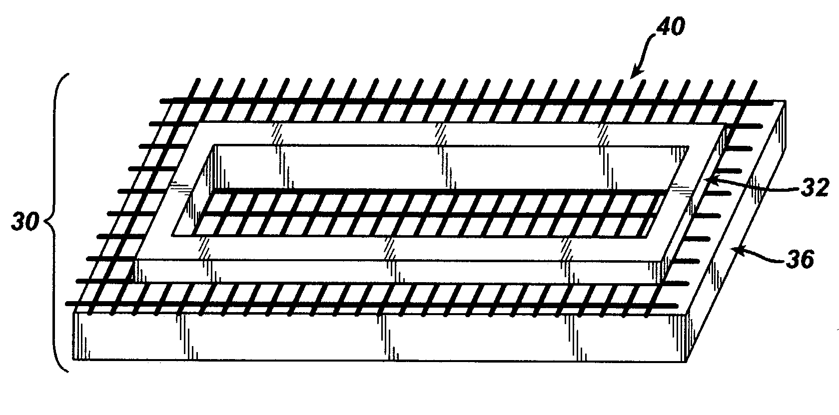
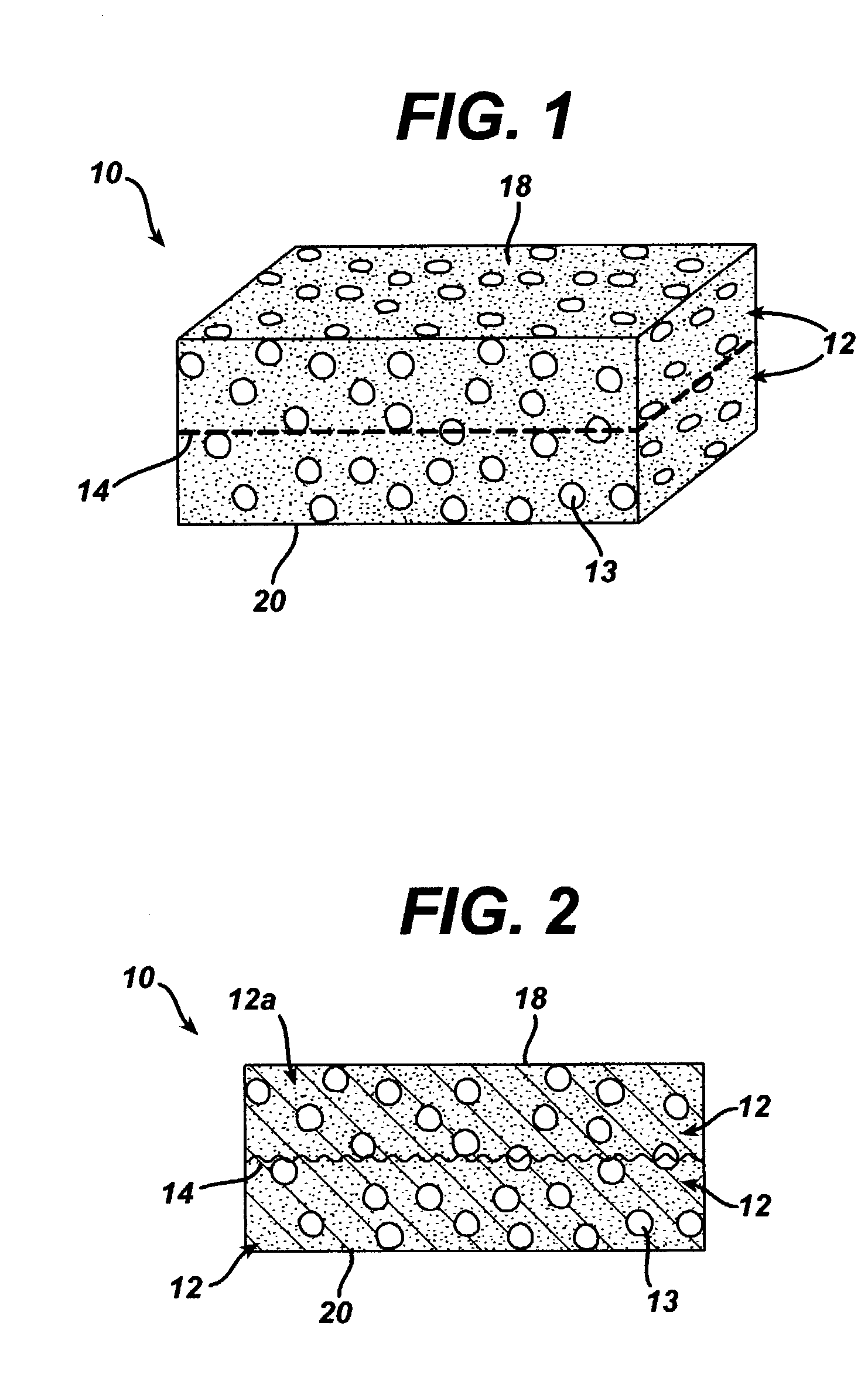
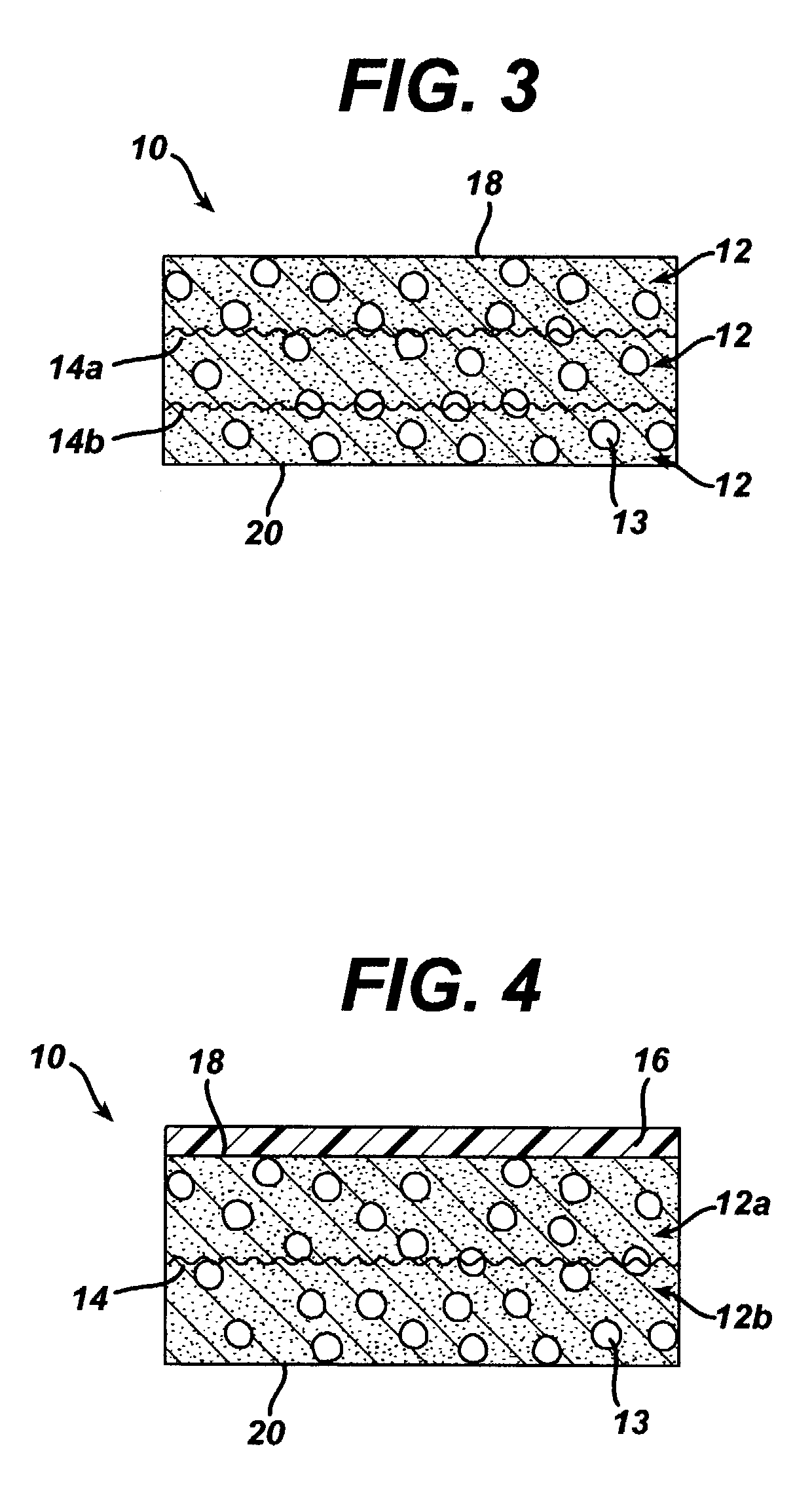
[0082]This example describes the preparation of a three-dimensional elastomeric tissue implant with a 95 / 5 poly(lactide-co-glycolide) mesh reinforcement produced according to the methods described in the existing art and in the manner as described in this work, namely quenching the mold assembly after adding the polymer solution.

[0083]A solution of the polymer to be lyophilized to form the foam component of both constructs was prepared. A 5% solution (by weight) of 60 / 40 poly(lactide-co-caprolactone) in 1,4-dioxane was made in a flask placed in a water bath stirring at 60° C. for 5 hours. The solution was filtered using an extraction thimble and stored in a flask.

[0084]The mesh used as the reinforcement in the constructs of this example was made from 95 / 5 poly (lactide-co-glycolide) yarn. Pieces of the mesh, cut to dimensions slightly larger than the stretcher and clamp apparat...

example 2

[0089]Annealed 95 / 5 poly(lactide-co-glycolide) yam mesh unquenched and quenched (constructs YAU and YAQ):

[0090]This example is identical to Example 1 with the exception that in this example, the 95 / 5 poly(lactide-co-glycolide) yarn mesh was annealed prior to processing.

[0091]The meshes were scoured according to the procedure delineated in Example 1. The scoured meshes were placed in stretcher and clamp devices used to hold the meshes flat and taut. The mesh / device assemblies were then placed in an inert gas annealing oven and annealed at 120° C. for 3 hours. The remainder of the experiment was conducted in the same manner as Example 1 with one annealed mesh being left unquenched and the other mesh being quenched. The lyophilization cycle was also the same.

[0092]It was found that the addition of the quenching step resulted in reinforced constructs in which less dissolution of the reinforcing fibers took place. Without quenching, regions of the mesh were observed to begin to dissolve ...

example 3

[0093]Unannealed 95 / 5 poly(lactide-co-glycolide) monofilament mesh unquenched and quenched (constructs MUU and MUQ):

[0094]The same procedure as described in Example 1 was used in this example with the exception that 95 / 5 poly(lactide-co-glycolide) monofilament was used to make the mesh instead of multifilament yarn. The only other difference was the size of the mold used. In this example, the same 5% (by weight) 60 / 40 poly(lactide-co-caprolactone) solution in 1,-4-dioxane was poured into smaller aluminum molds (15.3×7 cm2). Therefore, 40 g of polymer solution was sufficient to fully cover the bottom of the mold. Again, the meshes were scoured according to the procedure delineated in Example 1, and the scoured monofilament meshes constrained by the stretcher and clamp device were placed into the polymer-containing molds. One mold was placed directly on the shelf of the lyophilizer after placement of the mesh and lyophilized according to the cycle delineated in Example 1. The other me...


PUM

PropertyMeasurementUnit
Solubility (mass)aaaaaaaaaa
Freezing pointaaaaaaaaaa
Tensionaaaaaaaaaa

Abstract

A biocompatible tissue implant is disclosed. The tissue implant may be bioabsorbable, and is made from a biocompatible polymeric foam. The tissue implant also includes a biocompatible reinforcement member. The polymeric foam and the reinforcement member are soluble in a common solvent.

Description

FIELD OF THE INVENTION[0001]The present invention relates to bioabsorbable, porous, reinforced implantable devices for use in the repair of soft tissue injuries, and methods of using and manufacturing such devices.BACKGROUND OF THE INVENTION[0002]Injuries to soft tissue, including, for example, musculoskeletal tissue, may require repair by surgical intervention, depending upon factors such as the severity and type of injury. Such surgical repairs can be effected by using a number of conventional surgical procedures, for example, by suturing the damaged tissue, and / or by mounting an implant to the damaged tissue. It is known that an implant may provide structural support to the damaged tissue, and it may also serve as a substrate upon which cells can grow, thus facilitating more rapid healing.[0003]One example of a fairly common tissue injury is damage to or prolapse of the pelvic floor. This is a potentially serious medical condition that may occur during childbirth or from subseque...

Claims


Application Information

Patent Timeline
IPC IPC(8): A61F13/00A61F2/04A61L27/00A61F2/08A61F2/10A61F2/28A61L27/48A61L27/56A61M1/10
CPCA61F2/08A61L27/446A61L27/46A61L27/48A61L27/56C08L67/04A61F2210/0004A61L2430/34
Inventor CHUN, IKSOOJAMIOLKOWSKI, DENNIS D.BROWN, KELLY R.HWANG, JULIABINETTE, FRANCOISMELICAN, MORA CAROLYNNE
Owner DEPUY SYNTHES PROD INC
Why Eureka
Try Eureka