Radiation detector having coated nanostructure and method

a technology of nanostructure and radiation detector, which is applied in the direction of radiation measurement, optical radiation measurement, particle separator tubes, etc., can solve the problems of low detection efficiency of boron-doped diamond films, and low detection efficiency of light radiation such as x-rays

Inactive Publication Date: 2008-06-17
NANYANG TECH UNIV +3
View PDF14 Cites 23 Cited by
  • Summary
  • Abstract
  • Description
  • Claims
  • Application Information

AI Technical Summary

Problems solved by technology

Thus, radiation detectors have less than 100% detection efficiency.
However, detection efficiency for light radiations such as X-rays has not been reported and is expected to be lower.
Further, boron-doped diamond film can be expensive and the production cost for radiation detectors having boron-doped diamond film as the electron emitter can be high.
However, these techniques have limited applications and have limited effects.
For instance, the energy of radiation to be detected may not be controllable; the biasing voltage cannot be increased without limit.
However, in this approach, good quality of MgO coating can only be produced by electron-beam evaporation, which leads to certain drawbacks such as limited coating area and high cost of equipment and production.

Method used


Image

  • Radiation detector having coated nanostructure and method
  • Radiation detector having coated nanostructure and method
  • Radiation detector having coated nanostructure and method

Examples


Embodiment Construction

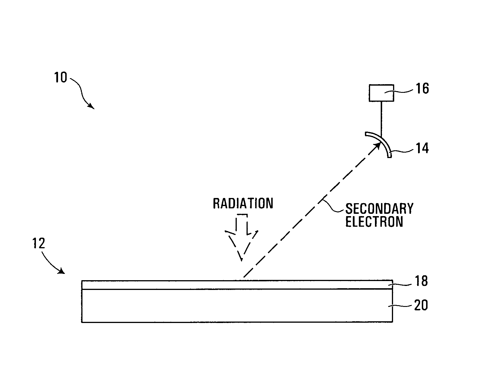
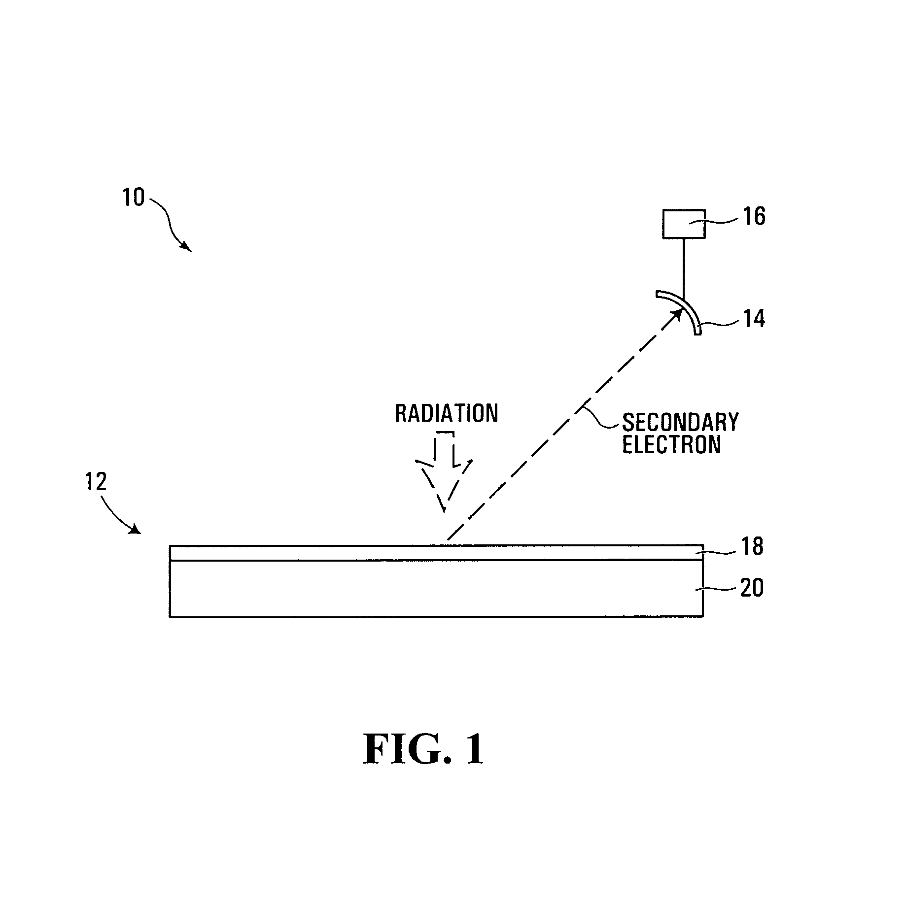
[0025]FIG. 1 is a simplified schematic diagram of a radiation detector 10, exemplary of an embodiment of the invention. Detector 10 includes an electron emitter 12, an electron collector 14 and a signal processor 16. As used herein, a radiation detector includes any radiation based detecting, sensing, or imaging device.

[0026]Electron emitter 12 has an emitting structure 18 formed on a support 20, which can emit secondary electrons under radiation of charged particles, photons or an electromagnetic wave. Charged particles can be electrons, protons, ions, and the like. Photon radiation can be light in UV portion of the spectrum, and the like. Electromagnetic radiation can be X-ray radiation and the like.

[0027]FIG. 2 illustrates an exemplary emitter 12. Emitting structure 18 is formed on a supporting surface 22 of substrate or support 20. Substrate 20 can be made from any suitable material on which emitting structure 18 can be formed, which will be described further below. Suitable mat...


PUM

PropertyMeasurementUnit
lengthaaaaaaaaaa
diameteraaaaaaaaaa
diameteraaaaaaaaaa

Abstract

A radiation detector has an electron emitter that includes a coated nanostructure on a support. The nanostructure can include a plurality of nanoneedles. A nanoneedle is a shaft tapering from a base portion toward a tip portion. The tip portion has a diameter between about 1 nm to about 50 nm and the base portion has a diameter between about 20 nm to about 300 nm. Each shaft has a length between about 100 nm to about 3,000 nm and an aspect ratio larger than 10. A coating covers at least the tip portions of the shafts. The coating exhibits negative electron affinity and is capable of emitting secondary electrons upon being irradiated by radiation. The nanostructure can also include carbon nanotubes (CNTs) coated with a material selected from the group of aluminum nitride (AlN), gallium nitride (GaN), and zinc oxide (ZnO). The detector further includes an electron collector positioned to collect electrons emitted from the electron emitter and to produce a signal indicative of the amount of electrons collected, and a signal processor operatively connected to the electron collector for processing the signal to determine a characteristic of the radiation. The detector can be used to detect radiations of changed particles or light such as X-ray.

Description

FIELD OF THE INVENTION[0001]The present invention relates generally to radiation detectors, and more particularly to radiation detectors having coated nanostructures and related methods.BACKGROUND OF THE INVENTION[0002]It is known to use detectors that have a secondary-electron emitter to detect radiation of charged particles or photons. The emitter can emit secondary electrons upon being irradiated. The emitted electrons are collected to produce a signal to indicate the presence or a characteristic, such as energy, of the radiation.[0003]Typically, not every radiation quanta incident on an electron emitter causes an emission. Thus, radiation detectors have less than 100% detection efficiency. It is desirable that a radiation detector has high detection efficiency.[0004]For example, PCT application publication WO 03 / 075299, published on Sep. 12, 2003, entitled “Device for detecting charged particles and photons,” to Bernd Fischer and Marian Cholewa (“Fischer”); and a report authored...

Claims


Application Information

Patent Timeline
Patent Type & Authority Patents(United States)
IPC IPC(8): G01N23/00
CPCG01T1/28Y10T428/2913
Inventor CHOLEWA, MARIANLAU, SHU PINGYI, GYU-CHULYOO, JIN KYOUNGBURDEN, ADRIAN PAULHUANG, LEIGAO, XINGYUWEE, ANDREW THYE SHENMOSER, HERBERT OSKAR
Owner NANYANG TECH UNIV
Why Eureka
Try Eureka