Apparatus and method for separating an analyte

a technology of analyte and apparatus, applied in the field of proteomics, can solve the problems of time-consuming and/or risky extraction procedures such as blotting or spot cutting, affecting the recovery and activity of proteins, and ms analysis disadvantages, so as to minimize the “dead” area between the compartments, minimize the number of molecules that penetrate into and minimize the effect of adsorption of molecules onto the chemical buffering system

Inactive Publication Date: 2008-06-24
DIAGNOSWISS
View PDF28 Cites 6 Cited by
  • Summary
  • Abstract
  • Description
  • Claims
  • Application Information

AI Technical Summary

Benefits of technology

[0046]In some embodiments of the invention, the “dead” area between the compartments is minimized, by making the compartments contiguous where they contact the chemical buffering means, so that only a very small portion of the chemical buffering means is not directly in contact with the sample solution. Such a geometry allows the number of molecules that penetrate into the chemical buffering system to be minimized. In this manner, the number of molecules that remain entrapped within the chemical buffering system at the end of the purification is minimized. Indeed, as the chemical buffering system is the only available passage for the current between two compartments, there is a very large density of current at the intersection between the chemical buffering system and two adjacent compartments. Due to the positioning of electrodes in each of the compartments, charged species migrating through this small portion of the chemical buffering system are directed towards the electrodes and hence towards the solution bulk of each reservoir. Only the molecules that are globally neutral in this small portion of the chemical buffering system will remain in it after the separation.
[0047]In another embodiment, a protective layer is added in the device of the invention in order to minimize the portion of the chemical buffering system contacting the sample solution. In this manner, adsorption of the molecules onto the chemical buffering system is minimized.

Problems solved by technology

Extraction procedures such as blotting or spot cutting are time consuming and / or risky for protein recovery and activity.
However, for MS analysis, the purity of the samples is critical and they generally have to be treated before measurements, which complicates the procedure.
Indeed, if the sample contains salts or other impurities, disadvantages can arise for MS analysis.
Moreover, the extraction method is not favorable for MS analysis since it leads to a high concentration of undesired compounds in the recovered sample.
So the major problem with 2D gel-electrophoresis is that the compounds to be analyzed are trapped within a gel and must be extracted and purified before further analyses.
In this case, the major disadvantage is that the final separated fractions contain a certain amount of undesired buffering species or ampholytes.
This is a problem since these additional compounds have to be removed before further analyses.
In the case of the immobilized buffering systems, the major disadvantage is that the final separated fractions are trapped in a gel or a membrane, which complicates further analyses.
However, this method requires the use of multiple compartments, multiple immobilized membranes and segmented pH gradients.
However, the device is not very convenient for modem life sciences such as proteomics, which requires high throughput techniques, with short purification time and optimized compound recovery.
Furthermore, the strong drawback of Off-Gel electrophoresis is that only components of pI=pH of the gel in contact with the chamber are recovered in solution.
It is indeed clear that any other proteins with pI close to the pH of the gel will migrate inside the gel and will be lost for further analysis.
Furthermore, preconcentration of sample is probably difficult to realize with Off-Gel electrophoresis, which is one of the bottlenecks of proteomics for analysis of low abundant proteins.
Indeed, such compounds do not have amphoteric properties (in contrast to e.g. proteins) and hence they always exhibit the same charge during the separation.
These electrophoretic separation systems therefore do not allow one to separate compounds according to their respective isoelectric point.
Indeed, the gels or membranes used in these systems do not comprise any buffering means to fix the pH, and these electrophoretic separation systems are thus fundamentally different from the aforementioned IEF apparatuses, since they are based on totally different separation principles.

Method used


Image

  • Apparatus and method for separating an analyte
  • Apparatus and method for separating an analyte
  • Apparatus and method for separating an analyte

Examples


example i

[0072]Methylene blue was obtained from Fluka. Immobiline DryPlates (pH range 4.0 7.0, 11 cm), which are immobilized pH gradient. (IPG) gels, were from Amersham Pharmacia Biotech. All the experiments were performed in MilliQ water.

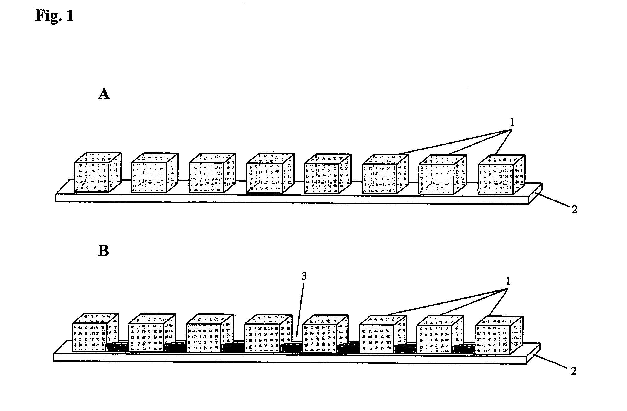
[0073]The multi-compartment set-up was a micro-titerplate (Millipore) composed of 96 (12×8) plastic wells (id 6 mm) opened at top and bottom extremities. In this experiment, the chemical buffering means comprises IPG gels that are cut to strips with a width of 7-8 mm, which is necessary to avoid solvent leakage. The length of the gel depended on the pH gradient to be distributed between the different wells. Reswelling of the gels was carried out for 1 hour at room temperature in water. The wells of the micro-titerplate were placed on top of the reswelled gel.

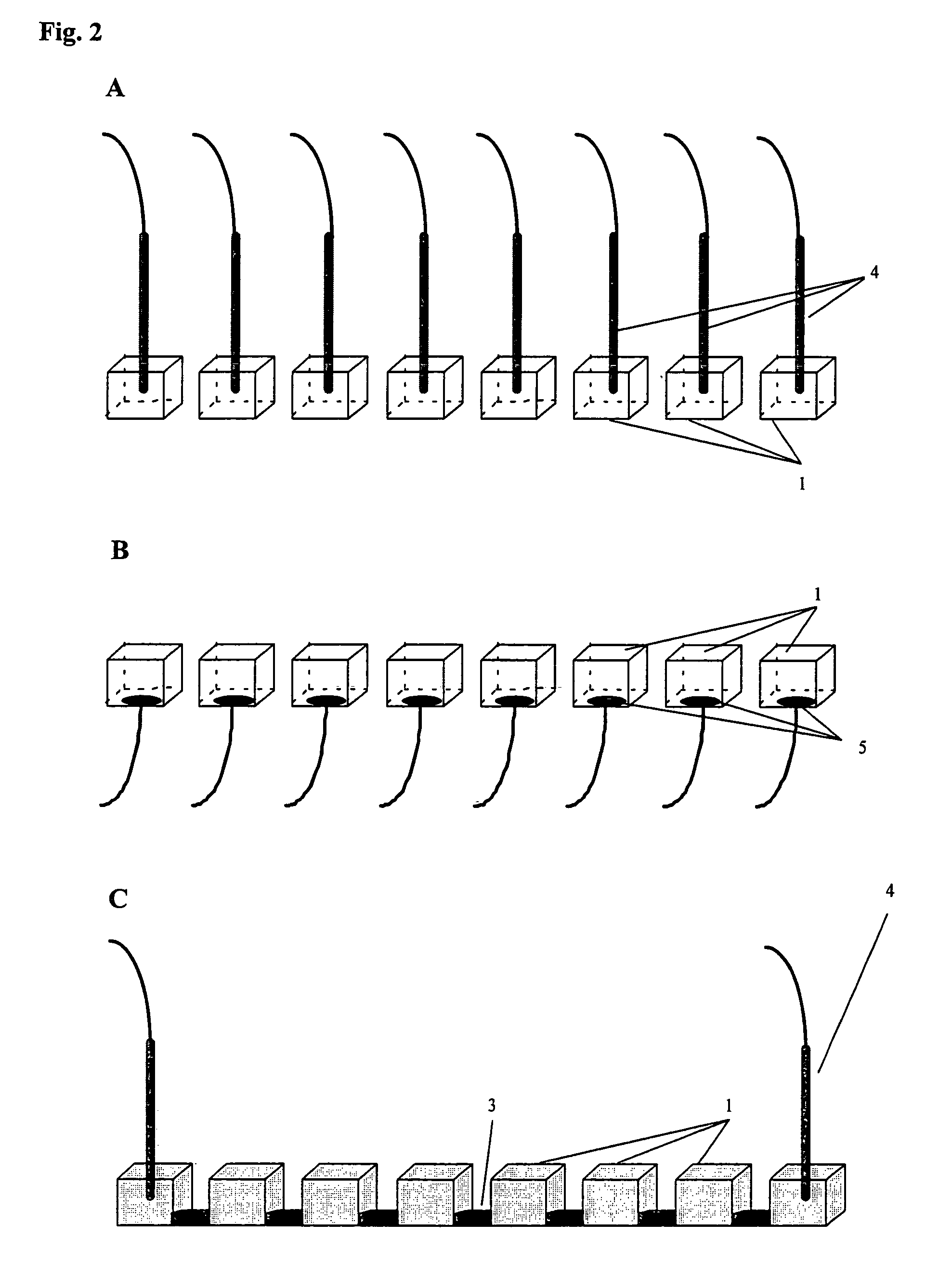
[0074]The wells were filled with 75 μl of analyte solution or water. A platinum electrode 4 was placed in the top extremity of each well. The electrodes were operated with a Landis & Gyr power supply. S...

example ii

[0079]β-lactoglobin B and equine myoglobin were purchased from Sigma. An aqueous solution of 500 μM β-lactoglobin B (pI=5.2) and 500 μM equine myoglobin (pI=7.0) was prepared. In this case, the experiment was performed using three adjacent wells placed on top of an immobiline gel, respectively on the pH 4.9, 5.2 and 5.6 lines. The other elements of the experimental set-up (multi-compartments, electrodes, chemical buffering system and power supply) were the same as in Example I above. The protein solution was placed in each of the three wells, which also contained an electrode. The experimental set-up used for this experiment is shown in FIG. 6.

[0080]MS assays were performed with an Ion Trap LCQ duo mass spectrometer (Finnigan) in a medium composed of 50 / 49 / 1 (v / v / v) CH3OH / H2O / CH3COOH. The experiments were performed at a flow-rate of 5 μl / min under a polarization of 5 kV.

[0081]The individual mass spectra of β-lactoglobin B and myoglobin are respectively presented in FIGS. 7 and 8. Th...

example iii

[0086]In order to demonstrate the unique feature of direct fluidic connection between the compartments, a comparison experiment between two multi-compartment IEF separations has been conducted whereby in one experiment, a direct fluidic connection is present (FIG. 13) and in the other, no direct fluidic connection is present (FIG. 14). The experiments have been conducted by means of 21 cm long polyurethane devices composed of 30 compartments. The direct fluidic connections were obtained by opening holes at the bottom of the walls separating the compartments. Control experiments were performed using the same prototype but without fluidic connections. The geometries of the non modified and modified devices are similar to the set-up respectively presented in FIGS. 4A and 4B. The polyurethane multi-compartment devices are compatible with the strip holders and with the IPGphor power supply from Amersham Biosciences which were used to perform electrophoretic separations.

[0087]Immobiline p...


PUM

PropertyMeasurementUnit
diameteraaaaaaaaaa
widthaaaaaaaaaa
pHaaaaaaaaaa

Abstract

The present invention relates to an apparatus and method for the separation and purification of charged and neutral compounds in an analyte solution by electrophoretic means using a plurality of compartments (1) to contain the analyte solution, an chemical buffering system (2) to fix a pH value or a pH gradient in its portion(s) contacting the analyte solution and an electrical field imposed by electrical means (4) disposed in at least two of said compartments. This invention allows one to differentially separate charged and neutral compounds, to extract the migrating compounds from the chemical buffering system (2), to recover the purified compounds mainly in solution and to collect them in the various compartments (4), preferably at various pI.

Description

[0001]This application is a 371 National Stage Entry of PCT / EP02 / 10369, filed on Aug. 30 2002.BACKGROUND OF THE INVENTION[0002]In the expending field of proteomics, complex biological samples that can contain up to 30,000 different proteins have to be separated and analyzed.[0003]Up to now, two-dimensional (2D)-gel electrophoresis has been the technique of choice to identify and classify proteins according to their isoelectric point (pI) and mass (Wilkins, M. R. et al., Proteome Research: New Frontiers in Functional Genomics; Springer, 1997). Indeed, with 2D-gel electrophoresis, proteins are separated first by an isoelectric focusing (IEF) step according to their pI. Secondly, proteins are separated as a function of their molecular mass by a polyacrylamide gel electrophoresis (PAGE) step. The proteins can thus be classified in databases according to their pI and mass.[0004]However, despite its extraordinary resolving power, it appears that 2D-gel electrophoresis has reached a platea...

Claims


Application Information

Patent Timeline
Patent Type & Authority Patents(United States)
IPC IPC(8): G01N27/447G01N27/453B01D57/02B03C5/00C07K1/28C12M1/34C12M1/38C12M1/42
CPCG01N27/44773G01N27/44795
Inventor ROSSIER, JOEL STEPHANEREYMOND, FREDERICMICHEL, PHILIPPE
Owner DIAGNOSWISS
Why Eureka
Try Eureka