Semiconductor device

a technology of semiconductor devices and semiconductors, applied in semiconductor devices, semiconductor/solid-state device details, electrical apparatus, etc., can solve problems such as shortage in photoresist exposure areas, new issues, and excessive lateral chip size, so as to reduce mutual inductance, reduce mutual inductance, and increase mutual inductance

Active Publication Date: 2008-06-24
SEMICON PATENT
View PDF3 Cites 12 Cited by
  • Summary
  • Abstract
  • Description
  • Claims
  • Application Information

AI Technical Summary

Benefits of technology

[0025]The present invention has been completed with the above issues in mind and has an object to provide a pad layout of a data family that has reduced inductance in wiring between pads of a chip and lands (pins) of a BGA package and a semiconductor device incorporating the pad layout to enable high-speed data transmission.
[0037]With the semiconductor device according to the present invention, the two rows of pad layouts are placed in the central area of the semiconductor chip and the pads are connected to the solder ball lands formed on the package substrate. The data pads of the semiconductor chip are placed in correspondence to layouts of respective solder ball lands for the data power source and the ground in checker patterns. This pad layout is located to decrease mutual inductance between the lead wires for the data power source and increase mutual inductance between lead wires for the data power source and the ground power source while minimizing effective inductance between lead wires for the data power source and the ground. This makes it possible to obtain a semiconductor device that has low noises in the data power source and the ground with capability of high-speed data transmission.

Problems solved by technology

However, applying the pad layout of the related art to DRAM with further high-capacity results in new issues.
With the chip in which the pads are placed in the chip center along the single row and memory cell arrays are located up and down, issues have occurred in that the chip size becomes too long in a lateral direction as shown in FIG. 7A and a shortage occurs in a photoresist exposure area on a production stage.
However, under situations where the related art pad layouts include data ground (VSSQ), two data (DQ) and the data power source (VDDQ) and are placed in the two rows, an undesirable consequence has turned out in that inductance causes disturbance in waveforms with the resultant inability of satisfying data transmission speed characteristic that is speeded up.
Thus, the data power source lead wiring has an adverse effect and has inductance which is equivalently doubled compared with that of the related art structure shown in FIG. 6.
Such an increase in inductance of the power source lead wire and ground lead wire causes an increase in power and ground noises, degradation in quality of an output signal on data (DQ) and degradations in a voltage margin of a device and a timing margin while causing negative impact on high frequency characteristic of the device during simultaneous switching when data is outputted.
Even with the 4-bit component, the same issues as those of the 8-bit component arise with the resultant occurrence of a factor causing deterioration in high frequency characteristic of the semiconductor device.
In such a way, it has turned out by the present inventors that both the 4-bit and 8-bit components have further deteriorated characteristics than those of currently available products and are not suited for high-speed data transmission.

Method used


Image

  • Semiconductor device
  • Semiconductor device
  • Semiconductor device

Examples


first embodiment

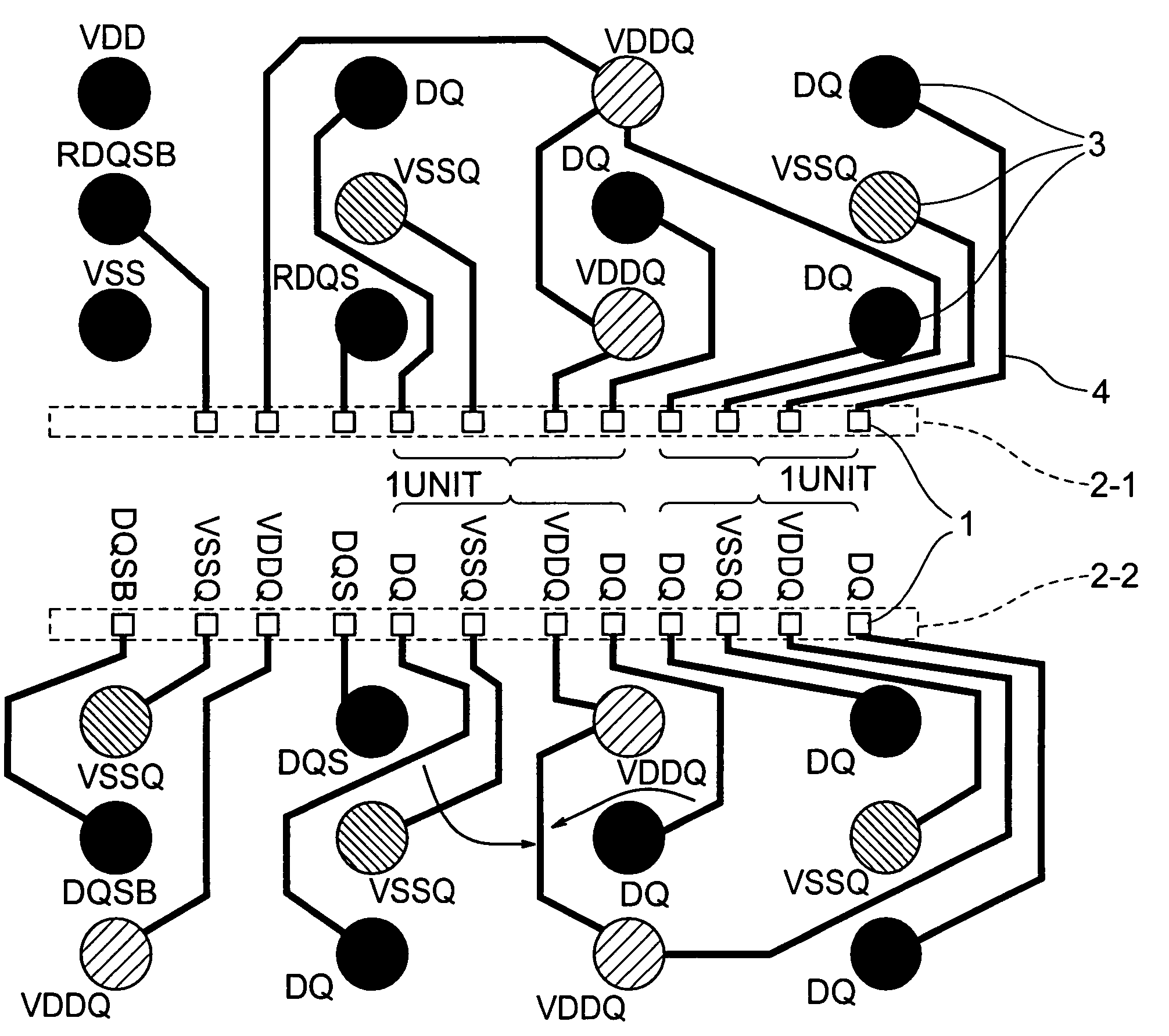
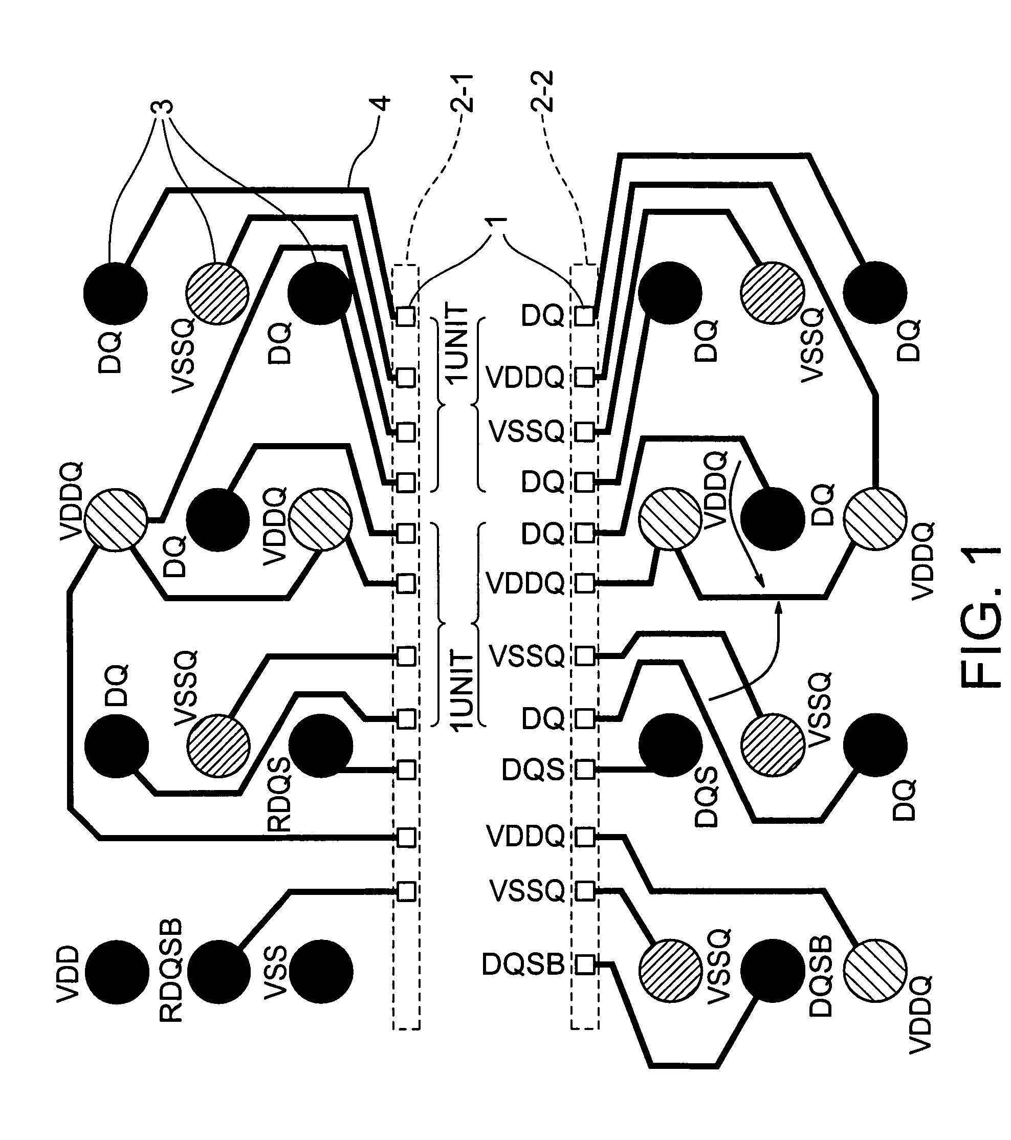
[0048]FIG. 1 is a pad layout of an 8-bit component of a first embodiment according to the present invention. FIG. 1 typically shows pads 1 of a semiconductor chip, solder ball lands 3 of a BGA substrate, and lead wires 4 by which the pads 1 and the solder ball lands 3 are connected to each other. Here, symbols “DQ”, “VDDQ” and “VSSQ” designating data, the data power source and data ground will also be used for solder balls (pins) and lands of the package, and for pads and lead wires of the semiconductor chip unless no particular confusion is caused.

[0049]In FIG. 1, the semiconductor chip has a central area on which pad layouts each including a plurality of pads 1 are disposed in upper and lower areas in two rows. The pads of the upper pad layout 2-1 are wire bonded to the solder ball lands 3 formed in the upper area, respectively, and the pads of the lower pad layout 2-2 are wire bonded to the solder ball lands 3 formed in the lower area, respectively.

[0050]FIG. 1 also typically sho...

third embodiment

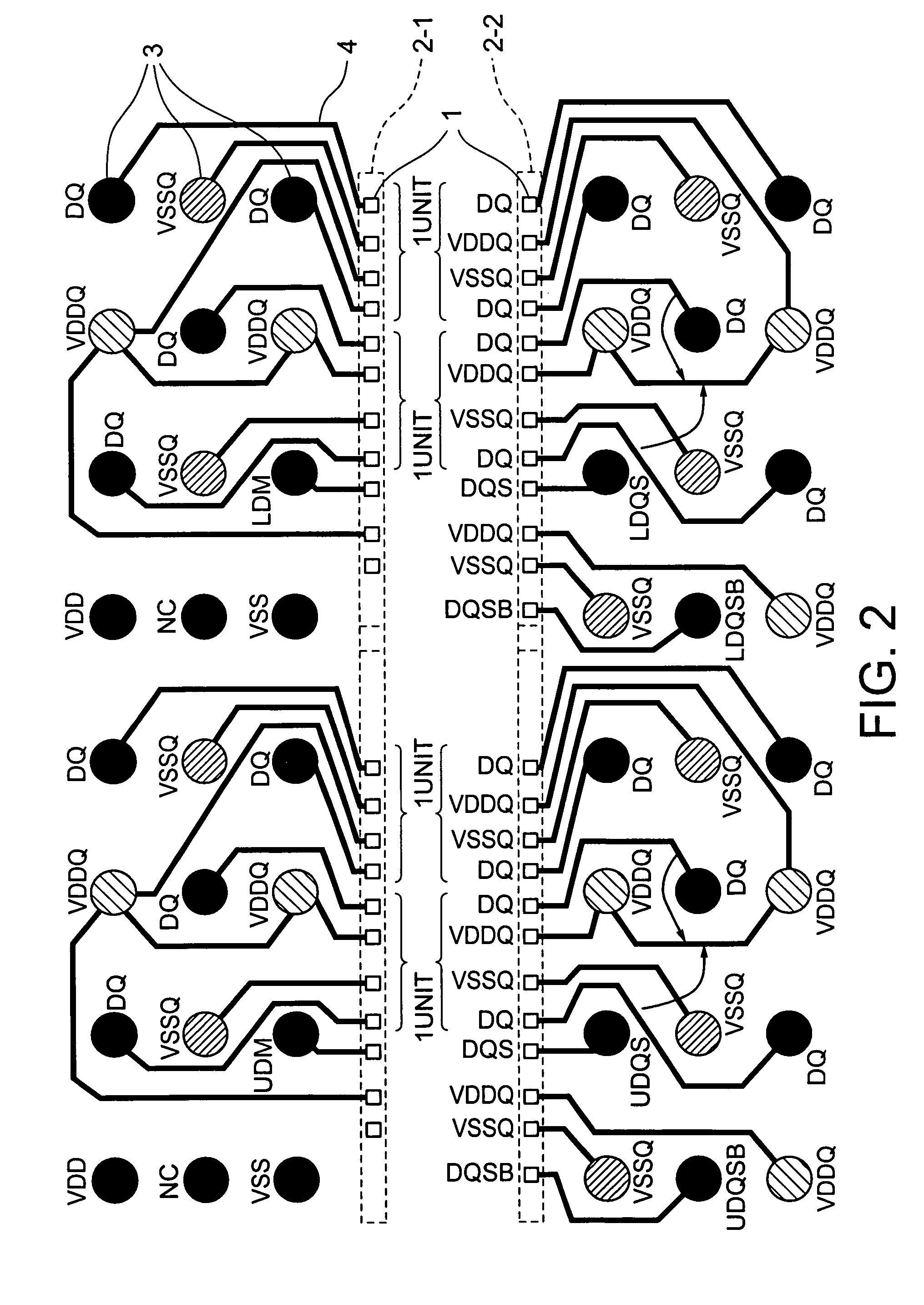
[0060]FIG. 3 shows a layout of a 4-bit component of a third embodiment according to the present invention. In FIG. 3, the 4-bit component can be structured upon removing unnecessary data bits from the structure of FIG. 1. With such a layout, the pads for the solder ball lands 3 corresponding to four pieces of data of a semiconductor chip remain under “NC (Non Connection)” and the land of the data strobe signal RDQS is converted to a data mask DM (Data Mask) signal. Among the 8 pads placed in the pad layout of S-G-V-S and the consecutive pad layout of S-V-G-S of the 8-bit component, the pads S on both ends are held under “NC” to provide six pads in layouts G-V-S and S-V-G. With such a structure, the pads for data power source (VDDQ) and data ground (VSSQ) are wire bonded in the same pattern as that of the 8-bit component.

[0061]In general practice, the 4-bit component employs the same semiconductor chip as that of the 8-bit component and product change is made upon selecting, for inst...

second embodiment

[0064]With the pads shown in FIG. 4, the data ground (VSSQ), data (DQ), the data power source (VDDQ) and data (DQ) are formed in one unit and the 8-bit component includes a unit in layout of G-S-V-S and the other unit in layout of S-V-S-G. The data ground (VSSQ) and the data power source (VDDQ) are located between which data (DQ) is sandwiched. With such a structure, no parallel placement of the data power sources (VDDQ) are achieved with the resultant reduction in mutual inductance between the data power sources (VDDQ) and increase in mutual inductance between the data power source and ground. This results in reduction of effective inductance between the data power source (VDDQ) and ground (VSSQ) and noises of the data power source and ground can be minimized whereby a semiconductor device available to achieve high-speed data transmission can be obtained. Moreover, by repeatedly placing the pad layout of the 8-bit structure shown in FIG. 4 in the same manner as the second embodimen...


PUM


Abstract

A semiconductor device is disclosed including a data family pad layout wherein an effort is made to contrive layouts of a power lead wire and a ground lead wire to minimize effective inductance in priority to a length of a lead wire between a pad and a solder ball land of a semiconductor chip. Pad layouts are arrayed in two rows and one unit of the pad layout is configured such that a data power source and ground are adjacent to each other or one data is inserted between the data power source and the ground. Such configurations decrease mutual inductance between the data power sources and increase mutual inductance between the data power source and the ground causing reduction in effective inductance between the data power source and the ground with the resultant minimization of power and ground noises.

Description

[0001]This application claims priority to prior Japanese patent application JP 2005-96741, the disclosure of which is incorporated herein by reference.BACKGROUND OF THE INVENTION[0002]1. Technical Field[0003]The present invention relates to semiconductor devices and, more particularly, to a semiconductor device in which a semiconductor chip has a central area on which pads are disposed and connected to terminals of a package.[0004]2. Related Art[0005]In recent years, attempts have heretofore been made to achieve the speeding up and large-scale integration of a semiconductor device while promoting the miniaturization of a package for downsizing the device. For a large-capacity storage device, a dynamic access memory (hereinafter abbreviated to DRAM) has been developed with a storage capacity in a gigabit class and mounted on a package in a small size. For the miniaturization of the package, a technology has been implemented to provide a ball grid array (hereinafter abbreviated to BGA...

Claims


Application Information

Patent Timeline
Patent Type & Authority Patents(United States)
IPC IPC(8): H01L23/48
CPCH01L23/50H01L23/5286H01L23/3114H01L2924/3011H01L2924/0002H01L2924/00
Inventor ISA, SATOSHIKATAGIRI, MITSUAKIOSANAI, FUMIYUKI
Owner SEMICON PATENT
Why Eureka
Try Eureka