

Chemical sensor
a technology of chemical sensors and fine particles, applied in the direction of heat measurement, beam/ray deflecting arrangement, optical radiation measurement, etc., can solve the problem of limiting the sensitivity of the sensor, and the difficulty in gaining a uniform size of metal fine particles in the metal colloidal solution within a deviation
- Summary
- Abstract
- Description
- Claims
- Application Information
AI Technical Summary
Benefits of technology
Problems solved by technology
Method used
Image

Examples
embodiment 1
[0044]A exemplary device configuration of a sensor device that uses a sensor medium in accordance with an embodiment of the present invention is shown in FIG. 4. In this example, a white light from a tungsten lamp 401 is collimated into virtually parallel lights by a collimating lens 402, and the lights enter a sensor medium 403. The lights that have transmitted through the sensor medium 403 enter a spectrometer 404, the spectrally resolved lights are detected by a multi-channel analyzer 405, and spectrum information is obtained.
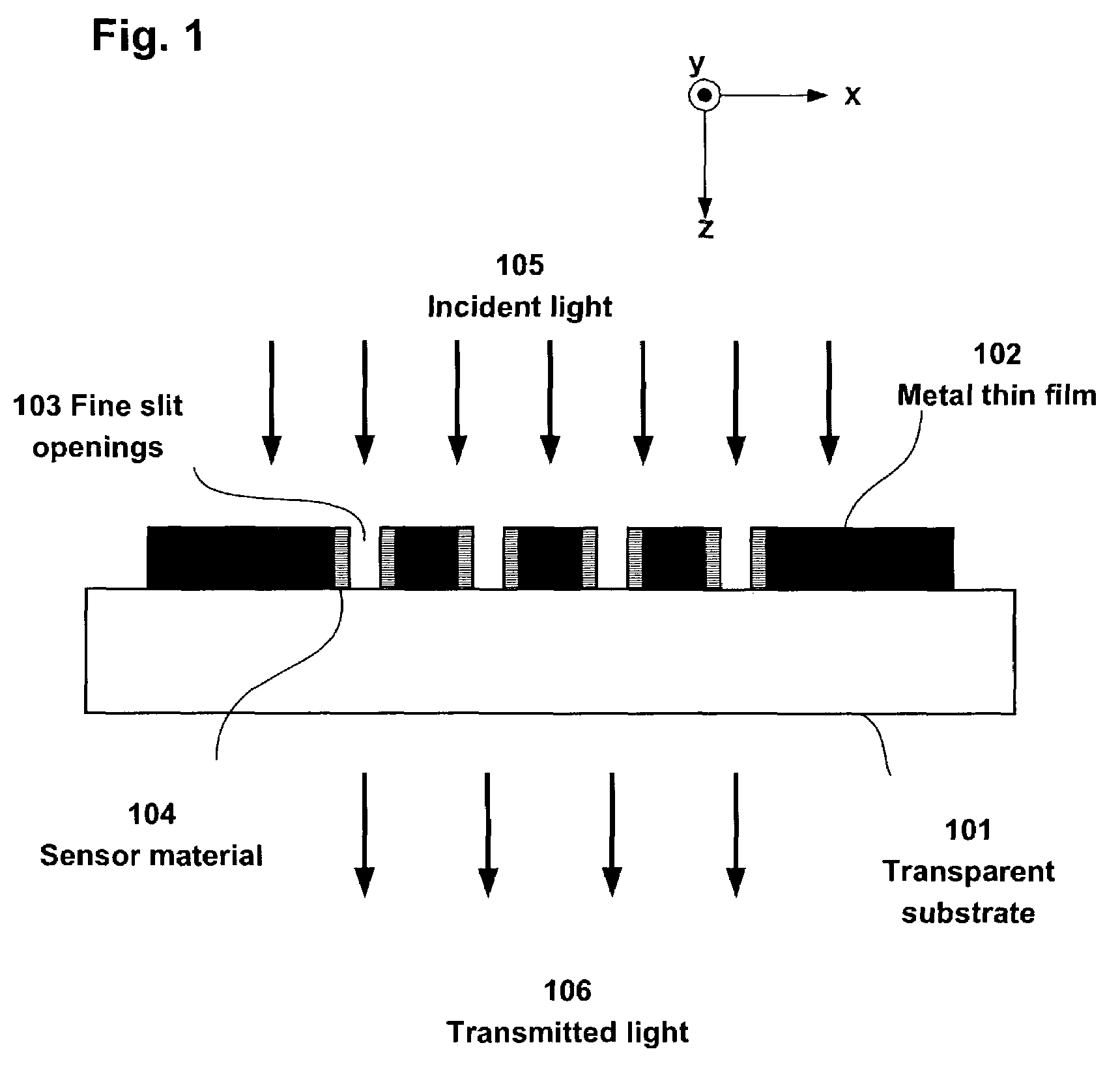
[0045]A material for the metal thin film (102 in FIG. 1) of the sensor medium is selected from among metals in general, but gold, silver, copper and aluminum especially generate large surface plasmon and are therefore desirable in the present invention. In particular, gold has a peak caused by localized plasmon resonance in the entire visible region and is consequently ideal to constitute a sensor that uses visible light for detection. In addition, by using ...
embodiment 2
ling
[0051]FIG. 7 indicates a multi-channel sensor medium, in which a plurality of slits and two-dimensional fine opening arrays 702-706 are provided in a metal thin film 701, as a sensor medium in accordance with an embodiment of the present invention.
[0052]The configuration of a multi-channel sensor device consisting of the multi-channel sensor medium is shown in FIG. 8. A light from a tungsten lamp 801 is collimated into virtually parallel lights by a collimating lens 802, and the lights enter a multi-channel sensor medium 803. A plurality of transmitted lights that transmitted through various fine opening arrays of the multi-channel sensor medium 803 go through filters A (804)-D (807), enter a CCD camera 808, and their transmission pattern information is obtained.
[0053]Through this process, relative spectrum information not dependent on the intensity of irradiated light can be obtained by having lights that passed through the same pattern, such as the fine opening array A (702) a...
embodiment 3
[0054]FIG. 9 is an example in which a sensor medium in accordance with an embodiment of the present invention is formed in a unitary fashion with a micro-chemical analysis system (called μ-TAS: micro-total analysis system or lab-on-a-chip).
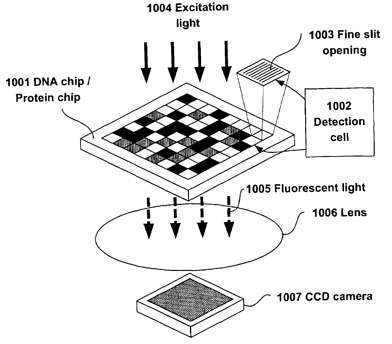
[0055]In a micro-chemical analysis system 901 in FIG. 9, a test solution injected into a sample solution injection section 902 passes through a flow path 904, reacts with a reaction solution injected into reaction solution injection sections 903, and reaches a detection section 905. As shown in an enlargement in the figure, fine slit openings 906 are provided in the detection section 905 for detection based on the principle of the present invention. The test solution seeps into the interior of the fine slit openings 906 and reacts with a sensor material inside the fine slit openings 906. An excitation light 907 is irradiated on the detection section 905; fluorescent lights 908 emitted from the fine slit openings 906 converge on a lens 909; the con...
PUM
| Property | Measurement | Unit |
|---|---|---|
| size | aaaaa | aaaaa |
| width | aaaaa | aaaaa |
| thickness | aaaaa | aaaaa |
Abstract
Description
Claims
Application Information