
Heat exchange foam

a heat exchange foam and foam material technology, applied in indirect heat exchangers, vacuum evaporation coatings, lighting and heating apparatus, etc., can solve the problems of difficult use in small devices and other applications, difficult to remove heat from small hot objects, and foam materials that do not utilize convective forces, etc., to achieve the effect of reducing the temperature gradient and increasing efficiency

Inactive Publication Date: 2008-07-22
UNIV OF VIRGINIA ALUMNI PATENTS FOUND
View PDF145 Cites 65 Cited by
  • Summary
  • Abstract
  • Description
  • Claims
  • Application Information

AI Technical Summary

Benefits of technology

The solution achieves heat transfer efficiency an order of magnitude better than conventional devices by maintaining a higher temperature across the heat exchanger, increasing radiation and conductive heat transfer rates, and allowing for scalability to larger systems while maintaining the benefits of micro heat pipe heat transfer.

Problems solved by technology

However, these foam materials transport heat by conduction through solid ligaments.
Because the ligaments need to be interspersed with open porosity to allow efficient heat transfer to occur to a cooling fluid, heat removal from small hot objects is problematic.
The foam materials do not utilize convective heat transfer processes and can be difficult to use in small devices and other applications.
They are also relatively heavy, unnecessarily rigid, and expensive to produce in full arrays.
Importantly, their ability to transfer heat by conduction and radiation is limited.

Method used


Image

  • Heat exchange foam
  • Heat exchange foam
  • Heat exchange foam

Examples


example 1

Production of Stochastic Open Cell Foam with Hollow Ligaments Using DVD

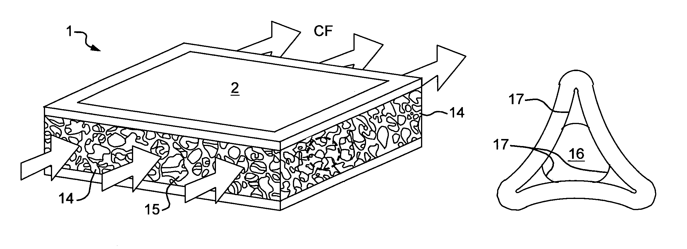
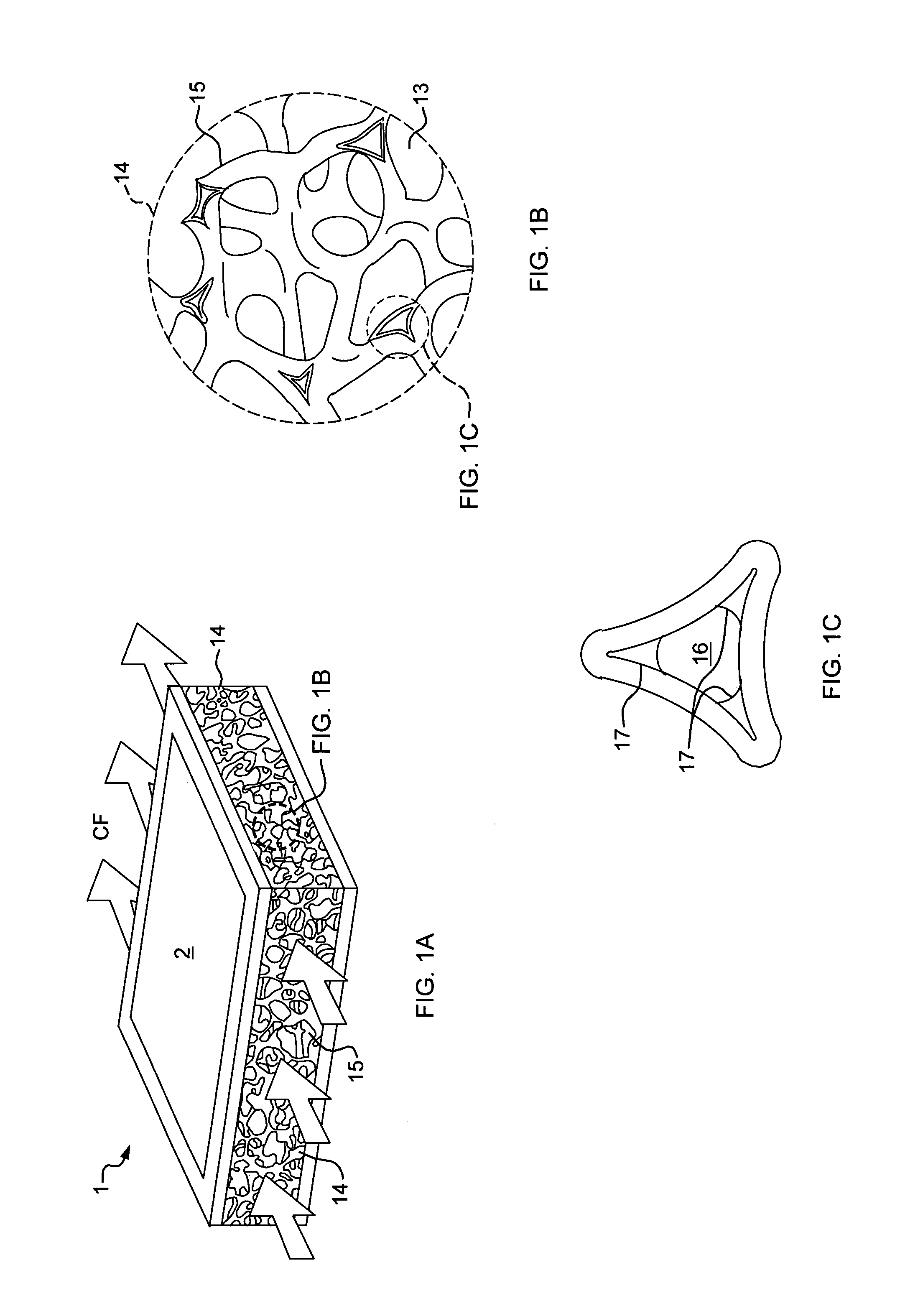
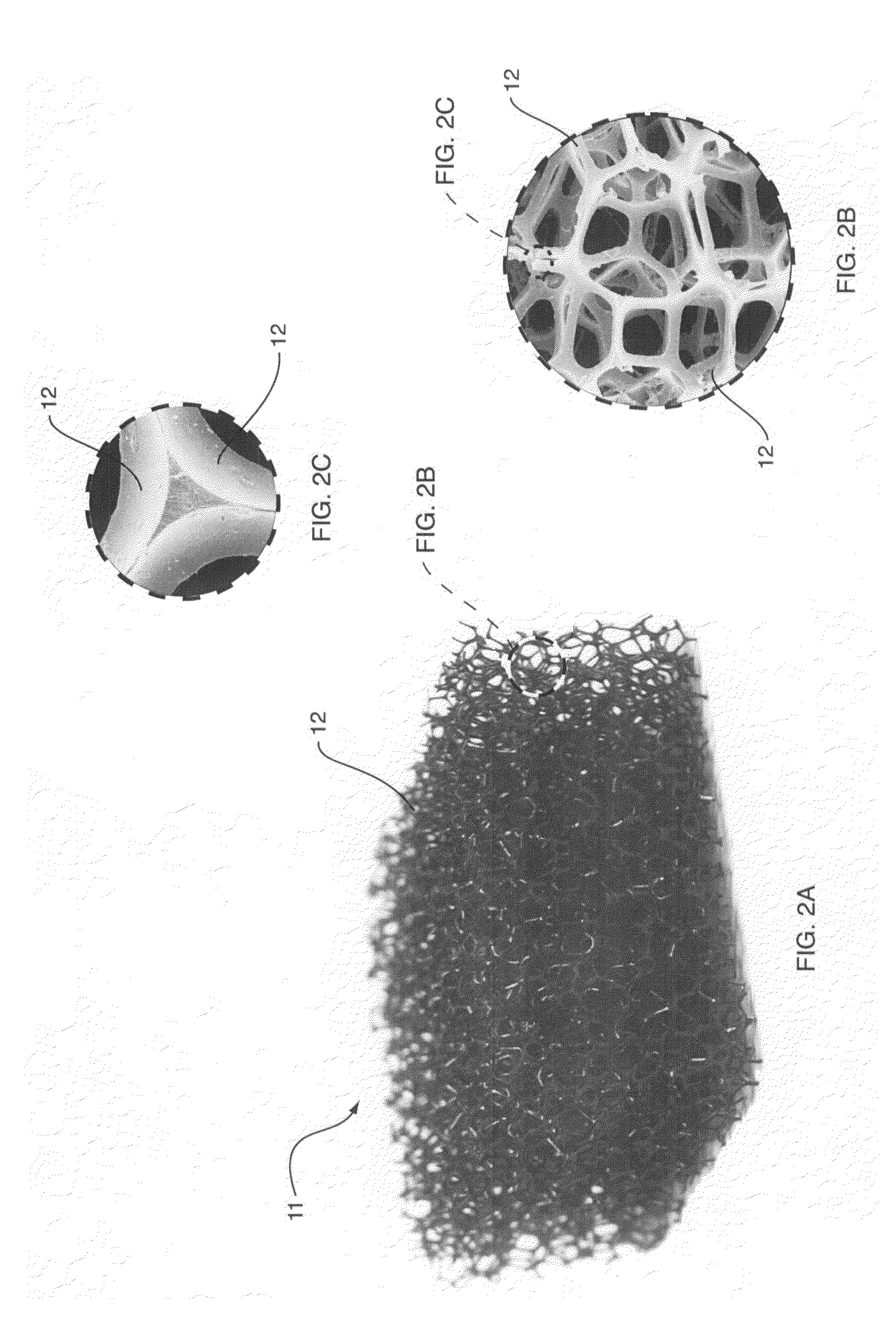
[0065]Turning to FIGS. 7A-7B, an open cell hollow foam 15 with hollow ligaments 16 that has been formed using the DVD machine and related method thereof, as shown in FIG. 4. The DVD machine allows, among other things the control of the following process variables: (1) electron beam power (measured in kilowatts (kW)), (2) carrier gas flow (measured in standard liters per minute (slm)), (3) chamber pressure (measured in Torr), (4) deposition time (measured in minutes), and (5) pressure ratio (the ratio of the nozzle pressure to the chamber pressure, a unitless number). FIG. 7A shows a photographic depiction of perspective view of the hollow foam 15 and FIG. 7B shows a micrographic depiction of a magnified partial view of the various hollow ligaments 16. The carrier gas used during the creation of such foam is helium, although a number of other non-reacting gases, like argon, and xenon are also preferred in some emb...

example 2

Filling the Internal Volume with Working Fluid in a Vacuum Chamber

[0078]Seal all ends of the hollow ligaments, except for those through which working fluid will be introduced into the internal volume. Place foam in a vacuum chamber and evacuate the chamber. While the chamber is still evacuated, charge the internal volume with the appropriate quantity of working fluid, possibly through the use of tubing to deliver the working fluid to the internal volume. Seal off the remaining ends of the hollow ligaments to prevent escape of the working fluid.

example 3

Filling the Internal Volume with Working Fluid Via Evaporation of the Fluid

[0079]Seal all ends of the hollow ligaments, except for those through which working fluid will be introduced into the internal volume. Charge the internal volume with a quantity of working fluid in excess of that amount desired to remain sealed in the internal volume, possibly by immersing the open ends of the hollow ligaments in a bath of the working fluid (working fluid will, for example, partially fill the internal volume via capillary action). Heat the working fluid to a temperature above its boiling point. The working fluid vapor will escape the internal volume and will evacuate the internal volume in the process. When the appropriate quantity of working fluid remains in the internal volume in liquid phase, seal off the remaining ends of the hollow ligaments.

[0080]By way of example, some preferred methods for sealing the ends of the hollow ligaments are (1) using an epoxy or other resin or glue to fill t...


PUM

PropertyMeasurementUnit
dimensionaaaaaaaaaa
pore sizeaaaaaaaaaa
pore sizeaaaaaaaaaa

Abstract

A method and an apparatus for the efficient transfer of heat utilizing micro heat pipes that include a cellular foam or interconnected cellular / truss network having hollow ligaments. A predetermined fraction of the internal volume of the hollow ligaments is filled with a carefully chosen working fluid, and the ends of the hollow ligaments are sealed. In operation, the working fluid evaporates in the region of high heat flux and condenses in regions of lower temperature, resulting in the transfer or redistribution of the fluid's latent heat of vaporization. For open cell foams and interconnected networks, a second fluid flowing through the open cells, separate from the working fluid but also in thermal contact with the hollow ligaments, assists in the transfer of heat from the foam and networks.

Description

RELATED APPLICATIONS[0001]This application is a national stage filing of International Application No. PCT / US01 / 22266, filed on Jul. 16, 2001, which claims benefit under 35 U.S.C. Section 119(e) from U.S. Provisional Application Ser. No. 60 / 219,149, filed on Jul. 14, 2000, entitled “Super Thermal Conducting Materials: Synthesis, Properties and Performance,” the entire disclosures of which are hereby incorporated by reference herein.GOVERNMENT SUPPORT[0002]Work described herein was supported by Federal Grant Number N00014-96-I-1028, awarded by the Office of Naval Research. The United States Government possesses certain rights in and to this invention.FIELD OF INVENTION[0003]This invention relates to a method and apparatus for the efficient transfer of heat, and more specifically to a three-dimensional micro heat pipe utilizing a hollow ligament foam or interconnected network, and the method of manufacturing the same.BACKGROUND OF INVENTION[0004]Heat exchangers are widely used to faci...

Claims


Application Information

Patent Timeline
Patent Type & Authority Patents(United States)
IPC IPC(8): F28D15/00C23C14/04F28D15/02F28D15/04F28F13/00
CPCC23C14/046C23C14/228F28D15/0233F28F13/003F28D15/0283F28D15/046F28D15/0275F28D2015/0225Y10S165/907Y02T50/60
Inventor QUEHEILLALT, DOUGLAS T.WADLEY, HAYDN N. G.KATSUMI, YASUSHI
Owner UNIV OF VIRGINIA ALUMNI PATENTS FOUND
Learn More