Adaptive dynamic range receiver for MRI

a dynamic range receiver and dynamic range technology, applied in the field of analog to digital conversion of signals, can solve the problems of high cost of downstream equipment that uses digital signals, quantization noise, and inability to address quantization noise, so as to avoid the need for costly analog signal processing circuits

Inactive Publication Date: 2008-07-22
FONAR
View PDF39 Cites 47 Cited by
  • Summary
  • Abstract
  • Description
  • Claims
  • Application Information

AI Technical Summary

Benefits of technology

[0014]By dividing the resonance signal among multiple channels, fixed-gain amplifiers (amplifiers with fixed components or variable-gain amplifiers whose gain is set and left undisturbed) may be employed. Also, down-conversion and all further signal processing may be performed digitally, avoiding the need for costly analog signal processing circuitry. Since range selection is automatic, there is no need to perform a calibration step when the sample (patient, patient position, section slice, etc.) is changed. The signal is automatically mapped to a channel for which the gain is optimal and changed to a different channel as soon as required. This avoids the need to determine the amplification required to map the raw signal to the full range of an ADC, as in the prior art. Calibration may be performed with a calibration signal from a built-in source for purposes of generating the table of complex multipliers. Also, while down-converting digitally requires high speed sampling of the raw signal and while high speed ADCs (e.g., 60 MHz-about 12 bits) are limited in terms of dynamic range, the processing of the signal, at times when it is very large, through a channel with low gain and, at times when it is very small, through a channel with high gain, insures that quantization noise remains a small proportion of the signal at all times. Note that while down conversion is discussed above as being performed after digitizing the amplified signals, the down conversion may alternatively be performed prior to digital conversion, for example, with the use of frequency down-converters.

Problems solved by technology

Quantization noise is a type of noise that results from error in the conversion of an analog signal to a digital form by an analog-to-digital converter (ADC).
When a smooth analog signal is transformed into a signal with steps, a certain amount of error results because portions of the analog signal between the steps must be converted to a signal that skips from one step to another rather than smoothly varying between them.
However, there are practical reasons for using the ADC with the smallest number of steps possible.
One is that using more steps can make the downstream equipment that uses the digital signal very expensive because each signal level must be encoded by a large amount of data.
The design of signal conditioning systems involving the conversion of analog signals to digital form invariably confronts the issue of quantization noise, although in most cases, it is just a routine step in the design process.
But in some kinds of signal analysis systems, such as Magnetic Resonance Imaging (MRI), quantization noise is not so easily addressed.
In MRI systems, this problem is acute because useful information is contained in the signal all the way down to the point at which its amplitude approaches zero.
The problem with handling such signals arises because of the large number of ADC steps required when a signal varies greatly in amplitude.
However, the amount of noise in the original analog signal places a lower limit on how much a greater number of steps will ultimately increase the quality of the digital signal.
Trying to reduce the magnitude of a very small quantization noise added to a signal that already has a much higher noise level, is wasteful because it takes a lot of computing power to handle a digital signal with a lot of amplitude steps.
Despite this, since the resonance signal can range over multiple orders of magnitude in a single imaging sequence, the amplification is such that the noise amplitude is still smaller than a step size, unless very expensive ADCs are used.
In practice, the prior art techniques applied heretofore have suffered from other sources of error and / or undue capital and operating costs, particularly in regard to the resonance signal analog processing.
But this solution to the dynamic range problem has drawbacks.
Analog amplification and down-conversion at such high frequencies makes the analog hardware particularly sensitive to introducing gain and phase error.
But even with a calibration, changing gain during operation can introduce errors that are not entirely mitigated by calibration-based compensation and even though careful design and component selection can mitigate them, the hardware costs are high.
The functional shortcomings of the analog down-conversion components place limits on the quality of images that can be produced and the increase the costs of signal processing equipment.
In addition, the calibration is a time-consuming nuisance that slows amortization and adds to the life-cycle costs of MRI systems.

Method used


Image

  • Adaptive dynamic range receiver for MRI
  • Adaptive dynamic range receiver for MRI
  • Adaptive dynamic range receiver for MRI

Examples


Embodiment Construction

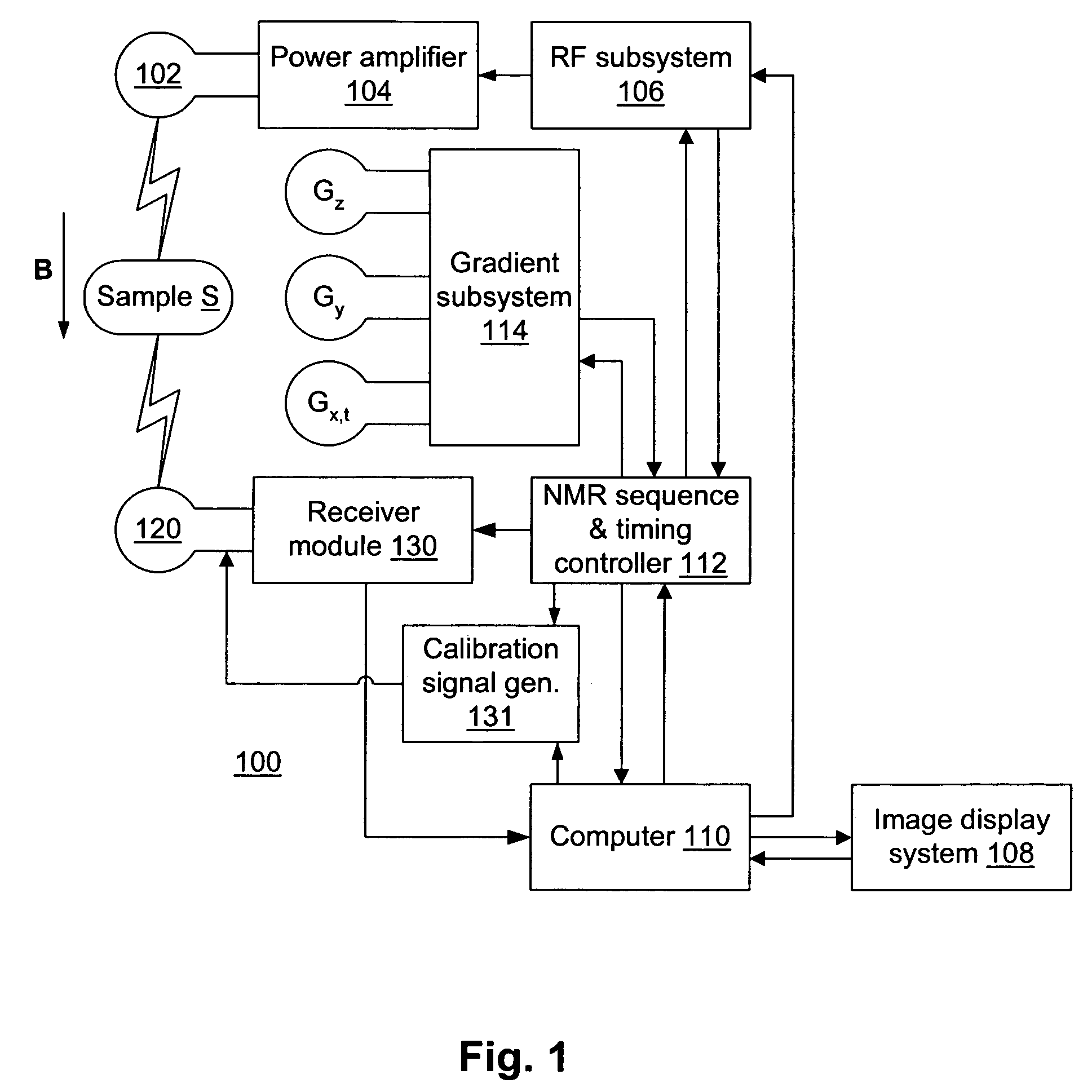
[0029]Referring to FIG. 1, a magnetic resonance imaging (MRI) system 100 has a transmitting coil 102 that injects radio frequency (RF) pulses into an imaging volume where a magnetic field B is maintained. The transmitting coil is driven by a power amplifier 104, which is in turn driven by a RF subsystem 106 under control of a computer 110 and a nuclear magnetic resonance (NMR) sequence & timing controller 112. A receiving coil 120 receives magnetic resonance (MR) signals, which are applied to a receiver module 130 for down-conversion to a baseband signal and error compensation. The resulting resonance signal is applied by the receiver module 130 to the computer 110 and image display system 108. Note that a single coil can be employed to transmit the RF signal and to receive the resonance signal. The computer 110 controls the NMR sequence & timing controller 112, which in turn controls a gradient subsystem 114 for the generation of orthogonal linear magnetic fields within the imaging...


PUM


Abstract

A receiver for a resonance signal of a magnetic resonance imaging system generates a baseband signal for image processing by dividing a raw resonance signal among multiple parallel channels, each amplified at a respective gain. A digital channel selector determines, at any given moment, a lowest-distortion channel to be further processed. Amplitude and phase error compensation are handled digitally using complex multipliers, which are derived by a calibration, based on a simple Larmor oscillator, which can be done without the need for a sample and without repeating when measurement conditions are changed. One of the important benefits of the invention is that it provides for gain selection without repeated calibration steps. This is particularly important in systems that employ fast imaging techniques such as fast spin echo, where the invention can speed imaging substantially.

Description

[0001]The present application is a continuation of application Ser. No. 10 / 646,401, filed on Aug. 22, 2003 now U.S. Pat. No. 6,943,548, which is incorporated by reference herein.FIELD OF THE INVENTION[0002]The present invention is directed to apparatus and methods for analog to digital conversion of signal characterized by wide dynamic range, and particularly to such apparatus and methods that are low in cost and require minimal calibration.BACKGROUND OF THE INVENTION[0003]Quantization noise is a type of noise that results from error in the conversion of an analog signal to a digital form by an analog-to-digital converter (ADC). Digital signals have discrete steps in amplitude, while analog signals can be smooth. So while an analog signal may rise or fall like a ramp, a digital signal rises or falls in discrete steps, like a staircase. When a smooth analog signal is transformed into a signal with steps, a certain amount of error results because portions of the analog signal between ...

Claims


Application Information

Patent Timeline
Patent Type & Authority Patents(United States)
IPC IPC(8): G01V3/00H03M1/00H03M1/18
CPCH03M1/188G01R33/3621
Inventor HERTZ, DAVID
Owner FONAR
Why Eureka
Try Eureka