Monitoring blood flow in the retina using a line-scanning laser ophthalmoscope

a laser ophthalmoscope and retinal blood flow technology, applied in the field of system and method of eye examination, can solve the problems of ischemic injury susceptibility, dimensions and flow parameters, fewer quantitatively, and few methods that can achieve dynamic blood flow imaging non-invasively (i.e., without dyes), and achieve the effect of high speed and efficient rejection of stray ligh

Inactive Publication Date: 2008-07-29
PHYSICAL SCI
View PDF4 Cites 75 Cited by
  • Summary
  • Abstract
  • Description
  • Claims
  • Application Information

AI Technical Summary

Benefits of technology

[0012]The invention, in one embodiment, features a line-scanning laser ophthalmoscope (LSLO) in conjunction with a high-speed retinal tracking system, which yields a tracking scanning laser ophthalmoscope (TSLO). The LSLO can image the retina by scanning a line of laser light, which can be confocal, with a linear sensor array or linear array detector. In one embodiment, the LSLO is therefore neither a true SLO nor a fundus camera, while possessing some of the advantages of both. These include efficient rejection of stray light and high speed read-out with no scanning on one axis (e.g., along the line). For each of these methods, light scattered from (z) planes above and below the focal plane can contribute to the image signals. For the SLO, the out-of-focus contributions fall off as 1 / z2, which provides its intrinsic optical sectioning capability. For the fundus camera with flood illumination, out-of-focus contributions (no z-dependence) are generally not rejected, which can account for its poor contrast. Finally, the LSLO can exhibit an approximate 1 / z dependence in its sensitivity to out-of-focus light, which can be regarded as an intermediate behavior or as “quasi-confocal.”
[0013]In one embodiment, the TSLO is configured for wide-field, large dynamic range stabilized Doppler flowmetry (SDF). Because of the high fidelity retinal tracking function, most eye motion artifacts can be eliminated, and the temporal spectrum at each pixel can be obtained. High contrast, low-noise, frequency-resolved retinal microvasculature and perfusion maps can then be visualized and recorded in a new dye-free angiography mode. With the novel imaging approach described below and advanced user interface features, the accessible Doppler frequency range for blood flow speeds can be significantly expanded both upwards and downwards, while eliminating confounding imaging artifacts and some limitations of earlier methods.
[0014]The addition of real time, high-speed retinal image stabilization is not merely a convenience. While retinal tracking can simplify some current clinical diagnostic protocols, and can reduce or eliminate registration issues by stabilizing relative to fixed retinal landmarks, its real contribution is potentially more fundamental. Tracking can enable the duration of any given scan or scan sequence to be effectively indefinite.
[0021]In one embodiment, the retinal tracking device locks a tracking beam onto a retinal feature and processes the backreflected signal from the tracking beam to stabilize the line-scanning laser ophthalmoscope. The retinal tracking device can track at a rate that exceeds the maximum rate of motion of an eye (e.g., having a bandwidth of greater than 1 kHz). In one embodiment, the retinal tracking device improves the resolution of the line-scanning laser ophthalmoscope.

Problems solved by technology

Like the central nervous system of which it is a part, it is also susceptible to ischemic injury.
This range of dimensions and flow parameters presents an extremely demanding diagnostic problem in terms of spatial resolution, field of view, and dynamic range.
Few methods accomplish dynamic blood flow imaging non-invasively (i.e., without dyes); fewer still quantitatively; and none with the wide field, high resolution, and dynamic range to characterize retinal hemodynamics globally.
In short, despite decades of research and the introduction of several advanced systems for measurement of blood flow, retinal blood flow Doppler imaging diagnostics have not yet achieved the clinical prominence that retinal biology would seem to justify.
Such variations are not intrinsic reflectivity variations, and so from a static imaging viewpoint, can be regarded as noise, with concomitant reduction of image contrast and spatial resolution.
Multiple scatterers within image volumes can give rise to some complex and often counter-intuitive characteristics for Doppler signals.
This dual-scatter enables velocities perpendicular to the incident beam to contribute to the Doppler signal, but can result in Doppler signals that have ambiguous spatial origin.
Multiple light scattering can cause these fine scales to lose contrast in flow images based upon Doppler frequency shifts.
Such measurements can be difficult to interpret for complex vessel topology.
Low data rates and high-frequency aliasing render the highest flows inaccessible and / or inaccurate.
Many scanning imaging technologies can suffer from practical limitations in the living eye as well at eye-safe light levels, e.g., scan areas or volumes and scan times are restricted by eye motions or other registration issues that corrupt data and are generally not correctable by post-processing.
This severely impacts the size of the measured fields and the trade-offs that need to be made in data quality.
The resulting difficulties of flow quantification, velocity range, sensitivity, dynamic range, and field of view have not yet been overcome by the prior art, especially for correlation of precise information about local anatomical features with the wide-field angiographic data familiar to clinicians.

Method used


Image

  • Monitoring blood flow in the retina using a line-scanning laser ophthalmoscope
  • Monitoring blood flow in the retina using a line-scanning laser ophthalmoscope
  • Monitoring blood flow in the retina using a line-scanning laser ophthalmoscope

Examples


Embodiment Construction

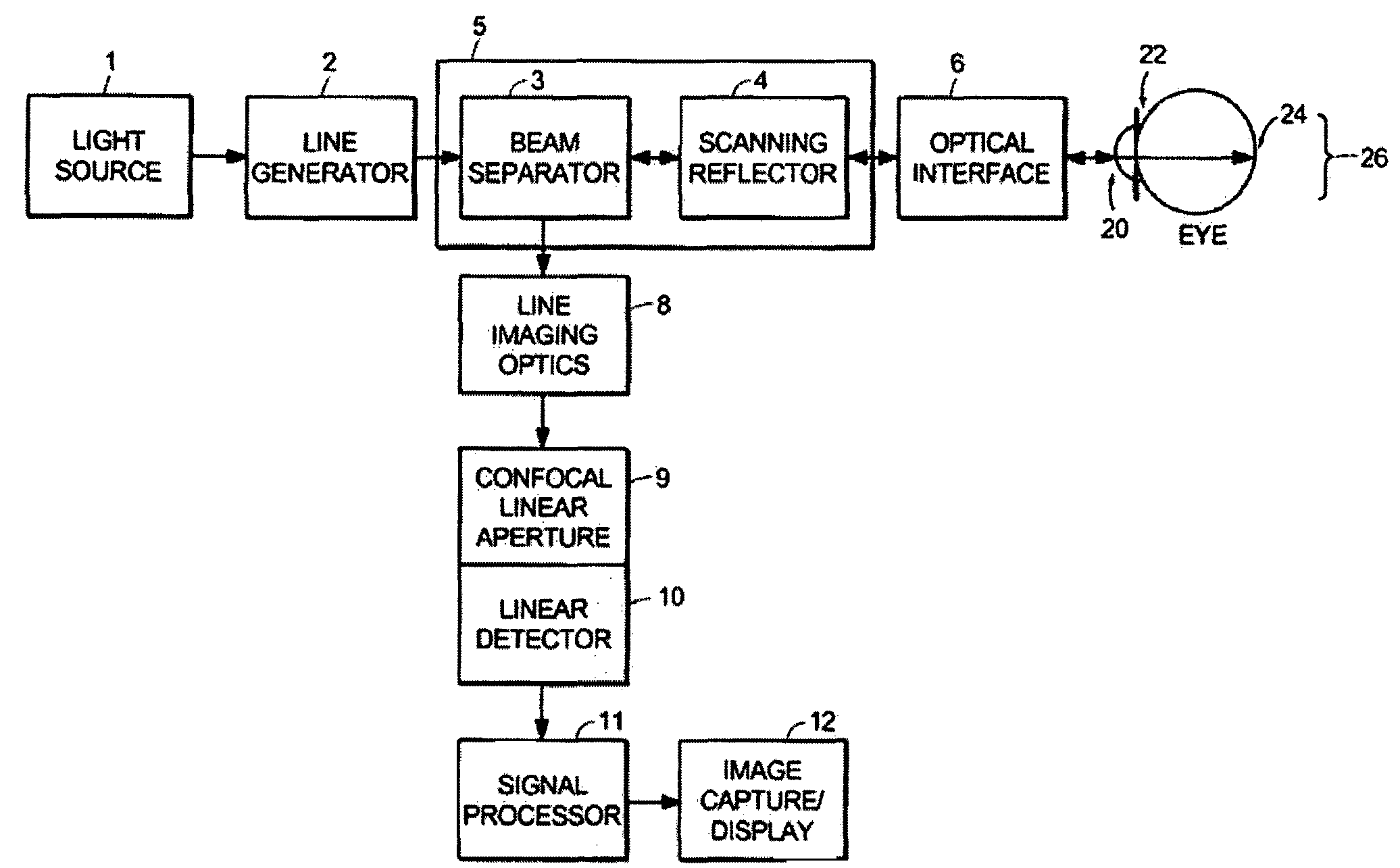
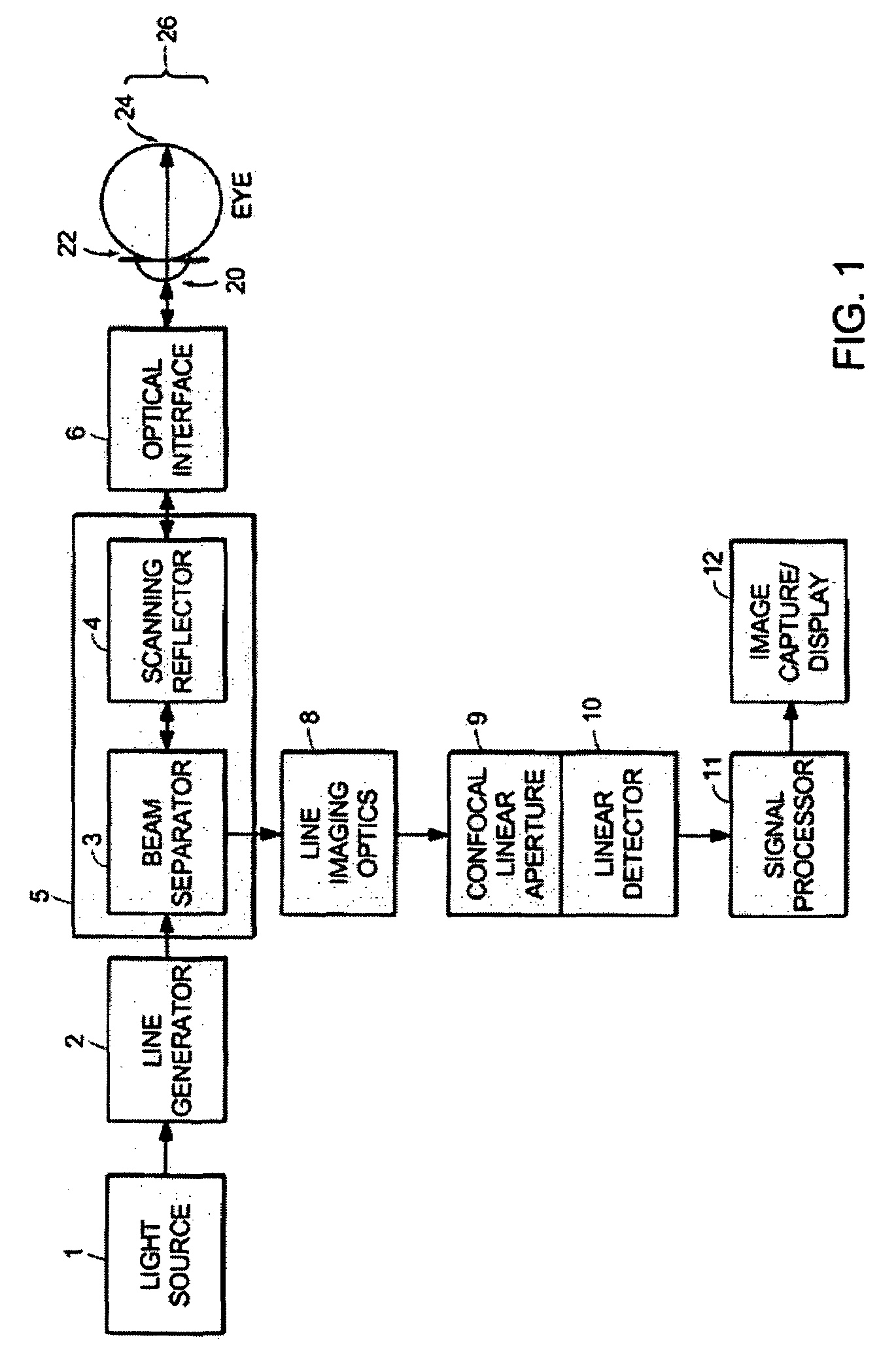
[0052]A line-scanning laser ophthalmoscope (LSLO) of the invention can have significant confocal advantages in image clarity and contrast and depth of penetration at the ocular fundus as compared with conventional digital fundus photography. A hand-held digital LSLO can capture high quality, non-mydriatic (e.g., undilated pupil), line-confocal retinal images; and stereo pairs can be obtained with a simple, compact design with fewer moving parts and components than prior SLO systems. In one embodiment, the system and method can involve a monostatic beam geometry, e.g., the light incoming to the object to be observed and the light collected in reflection from the object pass through the same location in space between the object and the optical component nearest the object. As a result of the monostatic beam geometry, the instrument can be operated with a small, undilated pupil. The instrument remains operative even if the pupil is dilated, however.

[0053]There are many benefits that ac...


PUM


Abstract

Real time, high-speed image stabilization with a retinal tracking scanning laser ophthalmoscope (TSLO) enables new approaches to established diagnostics. Large frequency range (DC to 19 kHz), wide-field (40-deg) stabilized Doppler flowmetry imaging is described for human subjects. The fundus imaging method is a quasi-confocal line-scanning laser ophthalmoscope (LSLO). The retinal tracking system uses a confocal reflectometer with a closed loop optical servo system to lock onto features in the ocular fundus and automatically re-lock after blinks. By performing a slow scan with the laser line imager, frequency-resolved retinal perfusion and vascular flow images can be obtained free of eye motion artifacts.

Description

CROSS-REFERENCE TO RELATED APPLICATION[0001]This application is a continuation-in-part of U.S. patent application Ser. No. 10 / 864,081 filed Jun. 9, 2004, which is a continuation of U.S. patent application Ser. No. 10 / 171,883 filed on Jun. 14, 2002, both of which are owned by the assignee of the instant application and the disclosures of which are incorporated herein by reference in their entireties.GOVERNMENT RIGHTS[0002]This invention was made with government support under Contract No. 1 R43 EY11819-01A1 awarded by the National Institute of Health / National Eye Institute. The government may have certain rights in the invention.FIELD OF THE INVENTION[0003]This invention relates generally to systems and methods for examining eyes. More particularly, the invention relates to systems and methods that employ scanned lines of light for examining eyes and monitoring blood flow in the retina.BACKGROUND OF THE INVENTION[0004]The retina is among the most highly vascularized and metabolically ...

Claims


Application Information

Patent Timeline
Patent Type & Authority Patents(United States)
IPC IPC(8): A61B3/10A61B3/12
CPCA61B3/1025
Inventor FERGUSON, R. DANIELHAMMER, DANIEL X.
Owner PHYSICAL SCI
Why Eureka
Try Eureka