Compression-evaporation system for liquefied gas

a compression evaporator and gas technology, applied in the direction of positive displacement liquid engines, container discharging methods, liquid fuel engines, etc., can solve the problems of high electricity consumption, large machine dimensions (typically 6 meters (m) tall), and high cost of terminal operation, so as to reduce or even eliminate the electricity consumption of a regasification lng terminal. , the effect of reducing or eliminating the electricity consumption

Inactive Publication Date: 2008-08-05
SN DETUDE & DE CONSTR DE MOTEURS DAVIATION S N E C M A
View PDF20 Cites 64 Cited by
  • Summary
  • Abstract
  • Description
  • Claims
  • Application Information

AI Technical Summary

Benefits of technology

[0021]The invention seeks to remedy the above-mentioned drawbacks and to make it possible to reduce or even eliminate the electricity consumption of a regasification LNG terminal.

Problems solved by technology

In particular, such technology constitutes a definite handicap for any off-shore application.
Furthermore, high pressure pumps 303 require a large quantity of electricity, which represents the most expensive financial outlay in the cost of running the terminal.
a) they are driven by non-regulated squirrel-cage asynchronous motors revolving at relatively low speed (3000 rpm to 3600 rpm) and they require a large number of stages (typically ten to 20) to achieve the require pressure rise;
b) such a pump arrangement having a large number of centrifugal stages leads to machines of large dimensions (typically 6 meters (m) tall) that are expensive, heavy, and bulky, and that are also relatively intolerant to any increase in the pressure in gas pipelines, should the need arise;
c) they are limited in flow rate by the power limitation of such motors (1 megawatt (MW) to 2 MW) and they need to be used in parallel in order to deliver gas at the rate required from the terminal; and
d) their motors are not regulated and their gas flow rate can be servo-controlled only by means of throttle valves located on the delivery outlet, and that technique is very penalizing in terms of electricity consumption.

Method used


Image

  • Compression-evaporation system for liquefied gas
  • Compression-evaporation system for liquefied gas
  • Compression-evaporation system for liquefied gas

Examples


Embodiment Construction

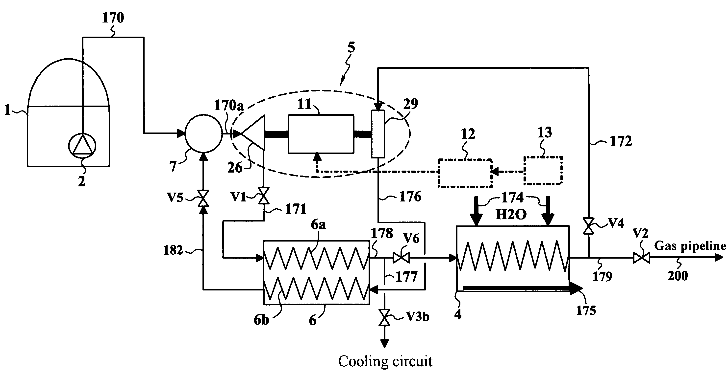
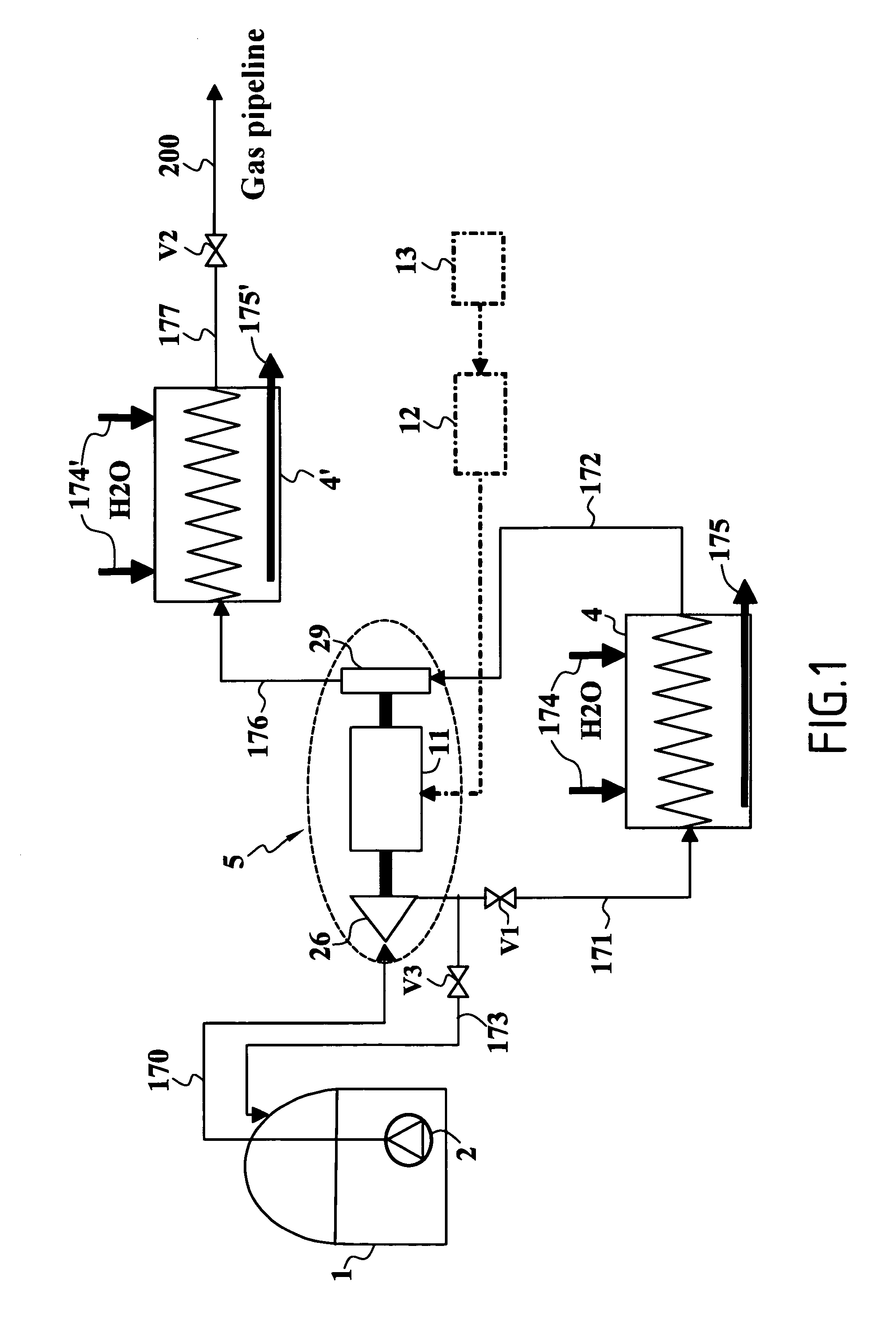
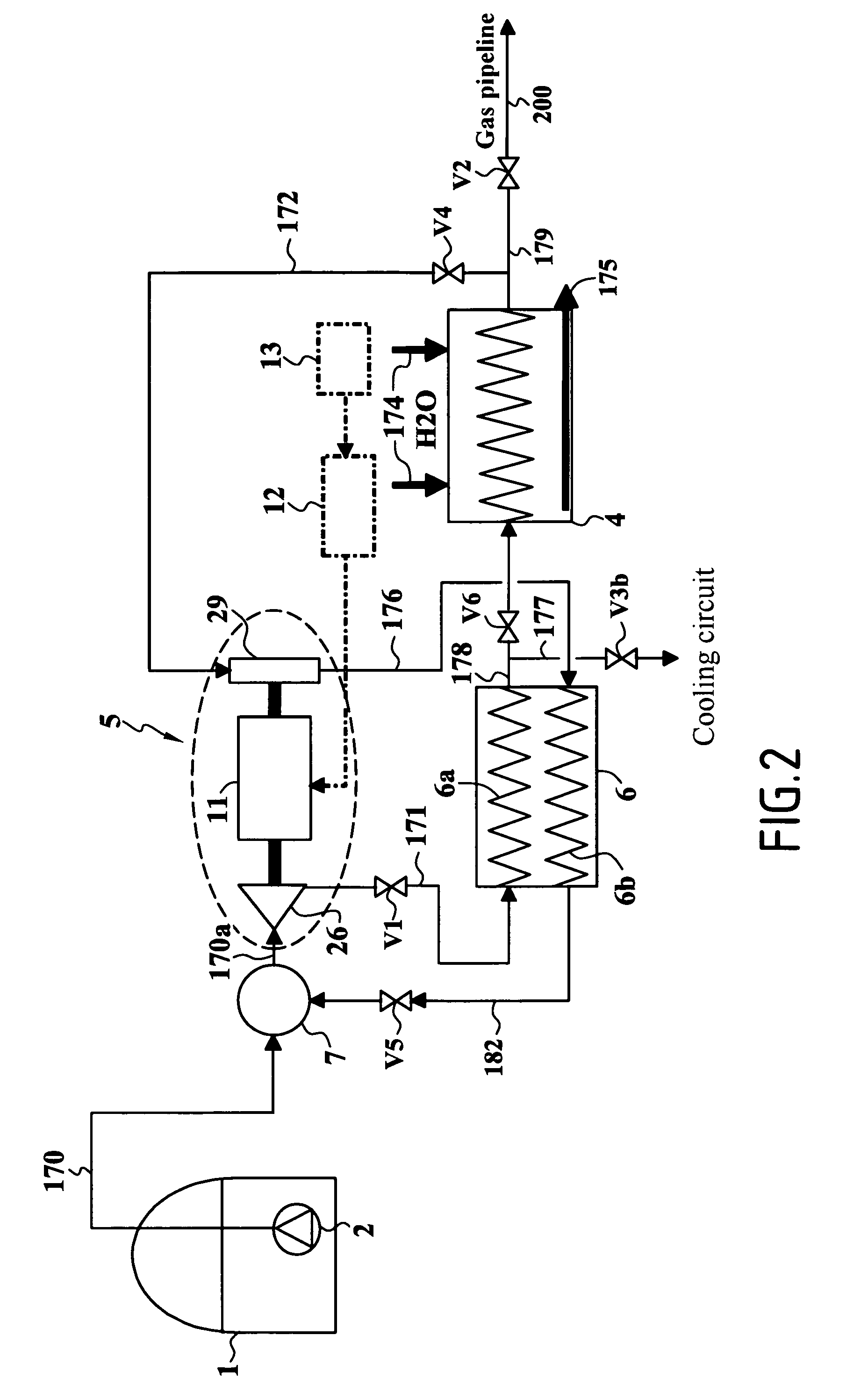
[0052]The invention applies in particular to a regasification terminal for LNG and seeks to reduce or even eliminate the electricity consumption of such a terminal by implementing a specific turbomachine referred to as a motor-driven turbopump (or MTP) suitable for application to various energy recovery cycles.

[0053]The invention relates to a compressor-evaporator system for liquefied gas which further comprises conventional means implemented to compress and heat and evacuate liquefied gas, i.e.: extraction and centrifugal pump means for delivering liquid gas at low pressure outside the tank; high pressure pump means and means for evaporation by heat exchange with water at ambient temperature or with hot water; and means for conditioning and transferring gas to a gas pipeline.

[0054]The compressor-evaporator system of the invention includes additional means comprising at least one specific turbomachine associated with one or more heat exchangers and with fluid flow and control equipm...


PUM


Abstract

The compressor-evaporator system for liquefied gas contained in a tank comprises, in addition to a deice for evaporation by heat exchange with a liquid and devices for conditioning and transferring gas to a pipeline, a motor-driven turbopump comprising a rotary assembly of high bending stiffness on a common shaft line, with at least one high pressure pump, a turbine, and a central electrical machine capable of being used in motor mode or in generator mode. The rotary assembly of the motor-driven turbopump is adapted to present a high speed of rotation, greater than 12,000 rpm, while remaining outside ranges for exciting critical speeds in rotation. All of the internal portions of the motor-driven turbopump are immersed in a cryogenic fluid that is the same as the liquefied gas contained in the tank. The internal cavities of the motor-driven turbopump that are under different thermodynamic conditions are separated by contactless dynamic seals. Electronic power circuits connected to an electricity network control the central electrical machine in motor mode or generator mode.

Description

[0001]This application claims priority to a French application No. 04 13486 filed Dec. 17, 2004.FIELD OF THE INVENTION[0002]The present invention relates to a compressor-evaporator system for liquefied gas contained in a tank, the system comprising extraction and pump means for extracting and delivering liquefied gas under low pressure outside the tank, high pressure pump means, evaporator means operating by heat exchange with a liquid, and means for conditioning and transferring gas to a gas pipeline.[0003]The invention relates to the general field of methods of regassing liquefied gases, and in particular it relates to liquefied natural gas (LNG).[0004]In practice, some of the natural gas that is extracted is liquefied in order to enable it to be conveyed in liquid form in tanker ships between production zones and zones where the gas is consumed. Such a gas transport system thus includes a liquefaction and storage terminal from which methane tankers are filled, and then take the l...

Claims


Application Information

Patent Timeline
Patent Type & Authority Patents(United States)
IPC IPC(8): F17C9/02F01K17/00F04B23/00
CPCF17C7/04F17C2270/0136Y02E20/14F17C2221/033F17C2223/0161F17C2223/033F17C2225/0123F17C2225/036F17C2227/0142F17C2227/0157F17C2227/0316F17C2227/0393F17C2260/046F17C2265/068F17C2265/05F17D1/02
Inventor VALENTIAN, DOMINIQUEFEGER, DAMIENMARCHAL, NOELDANGUY, FRANCOISLAGNEL, OLIVIER
Owner SN DETUDE & DE CONSTR DE MOTEURS DAVIATION S N E C M A
Why Eureka
Try Eureka