Catalytic combustors keeping contained medium warm in response to hydrostatic valve

a technology of catalytic combustors and hydrostatic valves, which is applied in combustion control, machine/engine, process and machine control, etc., can solve the problems of preventing the process of generating electricity, physical damage, and causing the initial inoperable of the fuel cell power plant, and achieves high efficiency

Active Publication Date: 2008-08-12
AUDI AG
View PDF4 Cites 12 Cited by
  • Summary
  • Abstract
  • Description
  • Claims
  • Application Information

AI Technical Summary

Benefits of technology

[0009]Objects of the invention include: maintaining the temperature of a medium within a container above a desired temperature without the use of electricity; keeping water, in an inoperative fuel cell power plant at subfreezing temperatures, from freezing without the use of electricity; efficient catalytic combustion of hydrogen; hydrogen / oxygen combustors which operate at temperatures below 150° C. (302° F.); catalytic combustors which can operate without any electrical controls; a keep warm heater for the accumulator of a fuel cell stack which operates without electricity; and high efficiency hydrogen / oxygen catalytic combustors.

Problems solved by technology

In PEM fuel cells, it is necessary to keep the anode side of the membrane from becoming dry, a condition which impedes the process of generating electricity.
When the fuel cell power plant is operating, it produces sufficient heat to maintain all of the water in the system above freezing; however, when the fuel cell power plant is inoperative at subfreezing temperatures for sufficient periods of time, water may freeze resulting in the potential for physical damage as well as causing the fuel cell power plant to be initially inoperable when startup thereof is desired.
), which causes inefficient operation of the combustor.

Method used


Image

  • Catalytic combustors keeping contained medium warm in response to hydrostatic valve
  • Catalytic combustors keeping contained medium warm in response to hydrostatic valve
  • Catalytic combustors keeping contained medium warm in response to hydrostatic valve

Examples


Embodiment Construction

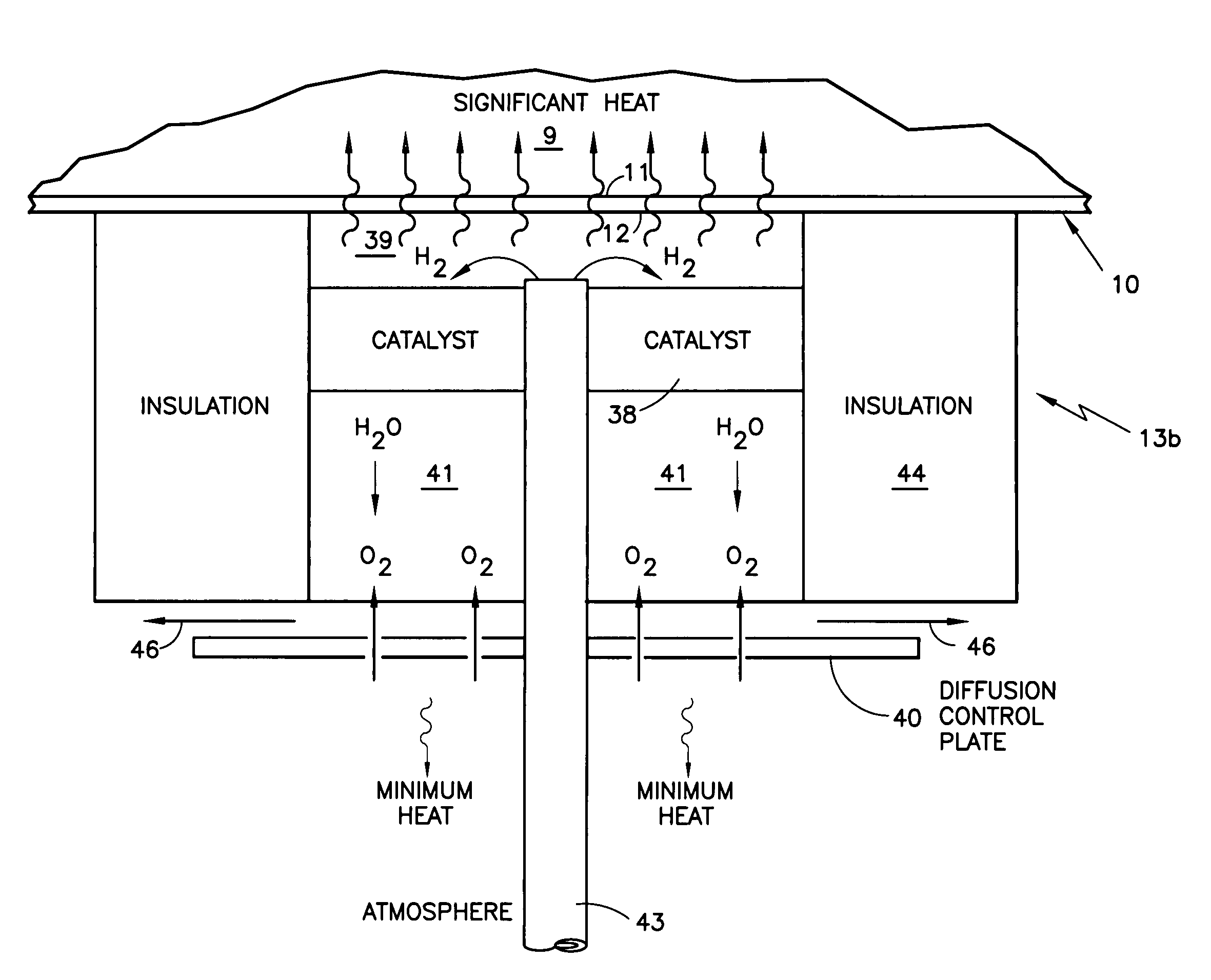
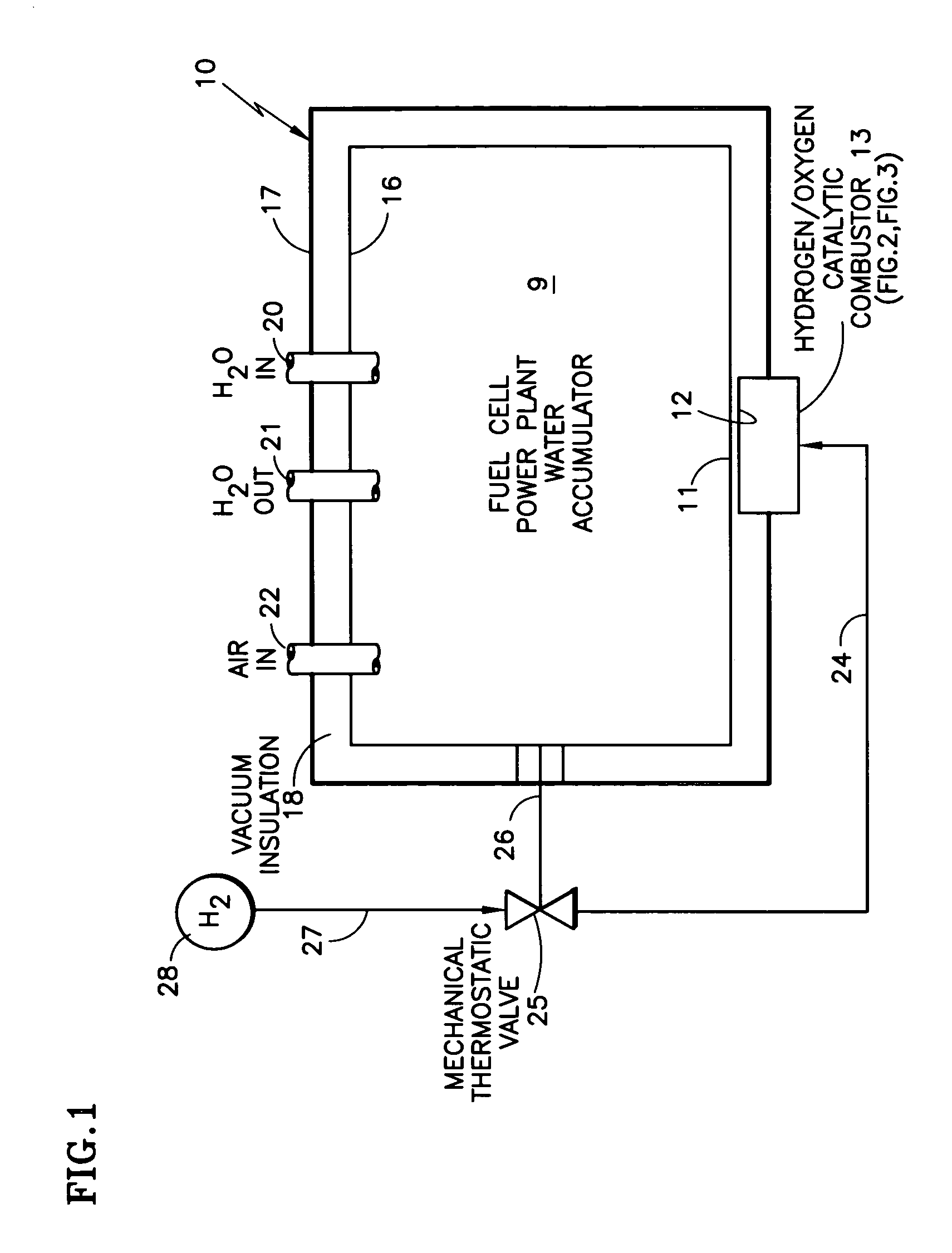
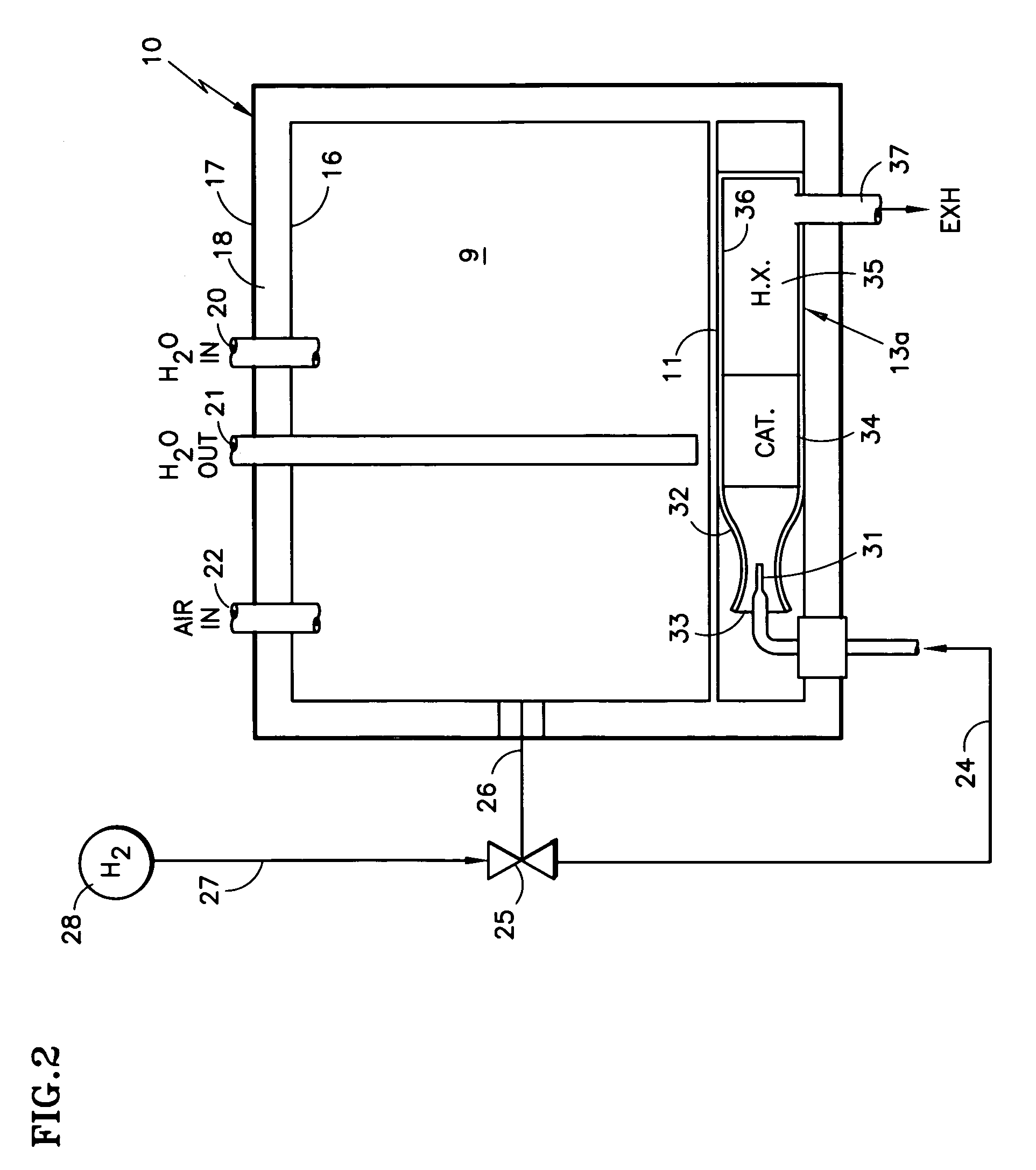
[0020]Referring to FIG. 1, a medium 9 within a container 10 is heated through a heatable surface 11 which is in thermal communication with a heating surface 12 of a hydrogen / oxygen catalytic combustor 13. The accumulator 10 may comprise a Dewar having inner and outer walls 16, 17 with vacuum 18 therebetween. The accumulator may have conventional water inlet 20 and outlet 21 and an air inlet 22.

[0021]The combustor 13 is provided with hydrogen over a conduit 24 from a source 25 which comprises a mechanical thermostatic valve, in thermal communication 26 with the container 10, the valve being connected by a conduit 27 to a supply of hydrogen under pressure 28. The hydrogen supply 28 may comprise the source of fuel reactant gas for a fuel cell power plant. The hydrogen may be substantially pure, or contained within a hydrogen-rich reformate or other gas.

[0022]The valve 25 is set so that it will become open if the accumulator 10 falls below a first temperature, and will close whenever th...


PUM

PropertyMeasurementUnit
temperaturesaaaaaaaaaa
temperatureaaaaaaaaaa

Abstract

The medium (9), such as water, of a container (10), such as a fuel cell accumulator, is kept above freezing by a hydrogen / oxygen catalytic combustor (13) fed hydrogen from a source comprising a mechanical thermostatic valve (25) in thermal communication (26) with the container (10) and connected to a hydrogen supply (28). The combustor may comprise an ejector (32) having hydrogen through its primary inlet (31) drawing air through a secondary inlet (33). The combustor may comprise a diffusion combustor having a catalyst (38) spaced from a heating surface (30) and a diffusion control plate (40) low partial pressure of oxygen at the catalyst causing diffusion through the barrier. Water vapor from combustion condenses on a surface (146) and is led by hydrophilic woven carbon paper (126) to wicking material (133), which has smaller pores than the carbon paper, which leads the water downwardly, through a disk (140) and plugs (147) to atmospheric air. The noble metal catalyst mixture includes TEFLON® to permit water generated by combustion to flow by gravity out of the catalyst.

Description

TECHNICAL FIELD[0001]This invention relates to catalytic combustors, including an ejector hydrogen / oxygen combustor and a diffusion hydrogen / oxygen combustor, for warming a medium within a container, such as water in the accumulator of a fuel cell power plant, in response to a mechanical thermostatic valve which conducts hydrogen to a combustor in dependence upon the temperature of the container.BACKGROUND ART[0002]Fuel cell power plants include a stack of fuel cells, each cell having anode and cathode catalysts surrounding an electrolyte, such as phosphoric acid or a proton exchange, polymer electrolyte membrane. In either case, one product of the process is water, which must be removed from the cathode in order to prevent flooding. In PEM fuel cells, it is necessary to keep the anode side of the membrane from becoming dry, a condition which impedes the process of generating electricity. Therefore, water management is important.[0003]In many applications, including stationary appli...

Claims


Application Information

Patent Timeline
Patent Type & Authority Patents(United States)
IPC IPC(8): F01N3/20H01M8/04
CPCF23C13/00F23C13/08F23D14/22F23D14/32H01M8/04022H01M8/04126H01M8/2475F23C2900/9901Y02E60/50F23N2037/12Y02E20/344F23N2025/18F23N2225/18F23N2237/12F23D14/18H01M8/04B01J8/02
Inventor REISER, CARL A.SAITO, KAZUOCAMERON, JAMESRESNICK, GENNADY
Owner AUDI AG
Why Eureka
Try Eureka