Sequential reaction system

a sequential reaction and reaction system technology, applied in the field of sequential reaction systems, can solve the problems of not being useful for most other chemical processing needs, not teaching or suggesting such an automated, sequential reaction system in the prior art, and one of the highest costs of research is associated with skilled labor

Inactive Publication Date: 2008-08-19
YMC
View PDF78 Cites 11 Cited by
  • Summary
  • Abstract
  • Description
  • Claims
  • Application Information

AI Technical Summary

Benefits of technology

[0009]In accord with the present invention, an automated sequential reaction system for sequentially producing a substance library of desired chemical products from a plurality of reactants is defined. Such an automated sequential reaction system includes a system controller adapted to monitor and control the production of the plurality of desired chemical products by the sequential reaction system, and a first automated reactant supply than includes a plurality of separate reactant chambers, each reactant chamber being adapted to be filled with a reactant. The automated reactant supply is controllably connected to the system controller, such that each reactant chamber can be selectively placed in fluid communication with a reaction module to provide a first reactant. In one embodiment, a supply valve i

Problems solved by technology

One of the highest costs of research is associated with skilled labor.
While the system disclosed by Neimark enables sequential reactions to be achieved, by its design, the system is optimized and essentially dedicat

Method used


Image

  • Sequential reaction system
  • Sequential reaction system
  • Sequential reaction system

Examples


Embodiment Construction

[0025]Exemplary Application of the Present Invention

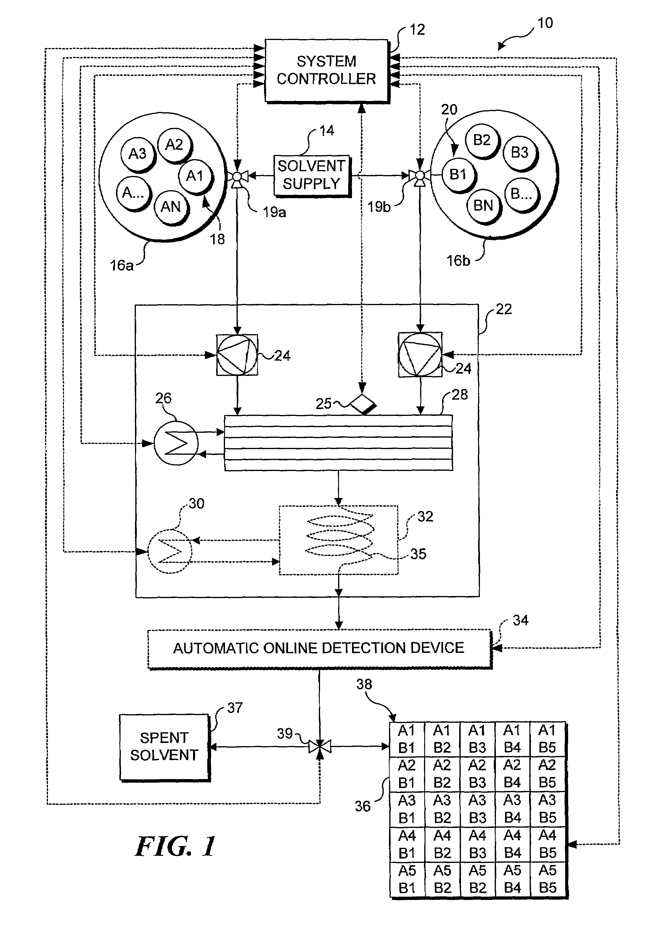
[0026]The automated sequential reactor system of the present invention can be continually operated to produce substance libraries, which are expected to be of great benefit in many phases of research. For instance, it is often useful to study how a particular chemical compound reacts with a group of related, yet different chemical compounds. As a specific example, consider an experimental compound “X” that is being studied as a potential raw material for producing a drug. In this example, it is assumed that “X” must be combined with a chemical compound that is a base (i.e., a compound having a pH over 7.0) in order to produce the drug. It would be desirable to react chemical “X” with a substantial number of different bases, to determine the yield from the reaction with each base. From the results of such tests, the relative costs of each base can be compared, to determine the base that produces the highest yield, at the lowest cost...


PUM

PropertyMeasurementUnit
Fractionaaaaaaaaaa
Fractionaaaaaaaaaa
Fractionaaaaaaaaaa

Abstract

An automated sequential reaction system that can be used to either sequentially produce a plurality of different products each requiring a single reaction, or to produce a desired product that requires a series of sequential reactions. A system controller controls an automated reactant supply, a solvent supply, a reaction module, a detector, and a product collector. Prior to initiating any reaction, the system is flushed with solvent and a heat exchanger supplies the reaction module with a temperature-conditioned fluid to maintain the reaction module at a desired temperature. For single reactions, a plurality of reactants are injected into a chemical reactor included in the reaction module. As fluid exits the chemical reactor, the detector determines if the fluid is a desired chemical product or solvent, and routes the fluid to the appropriate receptacle. Once a predetermined volume of a desired product is obtained, the system is flushed with solvent, and a different set of reactants are injected into the chemical reactor to produce the next desired product. The process is repeated until a substance library of the desired products is obtained. For products requiring sequential reaction steps, either a plurality of reactors are employed, or an intermediate product produced by a previous reaction is reintroduced into the reaction module with an appropriate reactant to complete the next sequential reaction.

Description

FIELD OF THE INVENTION[0001]This invention generally relates to a chemical processing apparatus, and more specifically, to a system for automatically controlling a plurality of sequential chemical reactions.BACKGROUND OF THE INVENTION[0002]Apparatus for controlling and optimizing the production of chemical substances are well known in the prior art. Factors affecting the design of chemical production equipment and of controlling the equipment include the chemical properties of the desired product and the reactants used, the temperature and pressure required, and the required product volume or production rate. Chemical processing equipment can be specifically designed for a particular reaction, or can be designed to be more generally applicable to a variety of chemical reactions.[0003]For example, the chemical processing equipment employed in large scale production facilities is often optimized for high volume production of a single desired product. In contrast, research laboratories...

Claims


Application Information

Patent Timeline
IPC IPC(8): B01J19/24B01J19/00C07B61/00C07C233/00
CPCB01J19/0046C07C233/00C40B40/04C40B50/08C40B60/14Y10T436/115831B01J2219/00337B01J2219/00389B01J2219/00495B01J2219/0059B01J2219/00686B01J2219/00689B01J2219/00704B01J2219/0072Y10T436/12B01J2219/00286
Inventor SCHWALBE, THOMASGOLBIG, KLAUSHOHMANN, MICHAELOBERBECK, ANDREASTAGHAVI-MOGHADAM, SHAHRIYAR
Owner YMC
Why Eureka
Try Eureka