

Gas purge system and methods
a technology of gas purge system and purge method, applied in the direction of optical radiation measurement, instruments, spectrometry/spectrophotometry/monochromators, etc., can solve the problems of sensitive measurement technique providing unmatched capabilities for thin film metrology, and achieve the effect of fast purge time, large purge volume, and relatively slow purge tim
- Summary
- Abstract
- Description
- Claims
- Application Information
AI Technical Summary
Benefits of technology
Problems solved by technology
Method used
Image

Examples
Embodiment Construction
[0012]Although the following detailed description contains many specific details for the purposes of illustration, anyone of ordinary skill in the art will appreciate that many variations and alterations to the following details are within the scope of the invention. Accordingly, the exemplary embodiments of the invention described below are set forth without any loss of generality to, and without imposing limitations upon, the claimed invention.
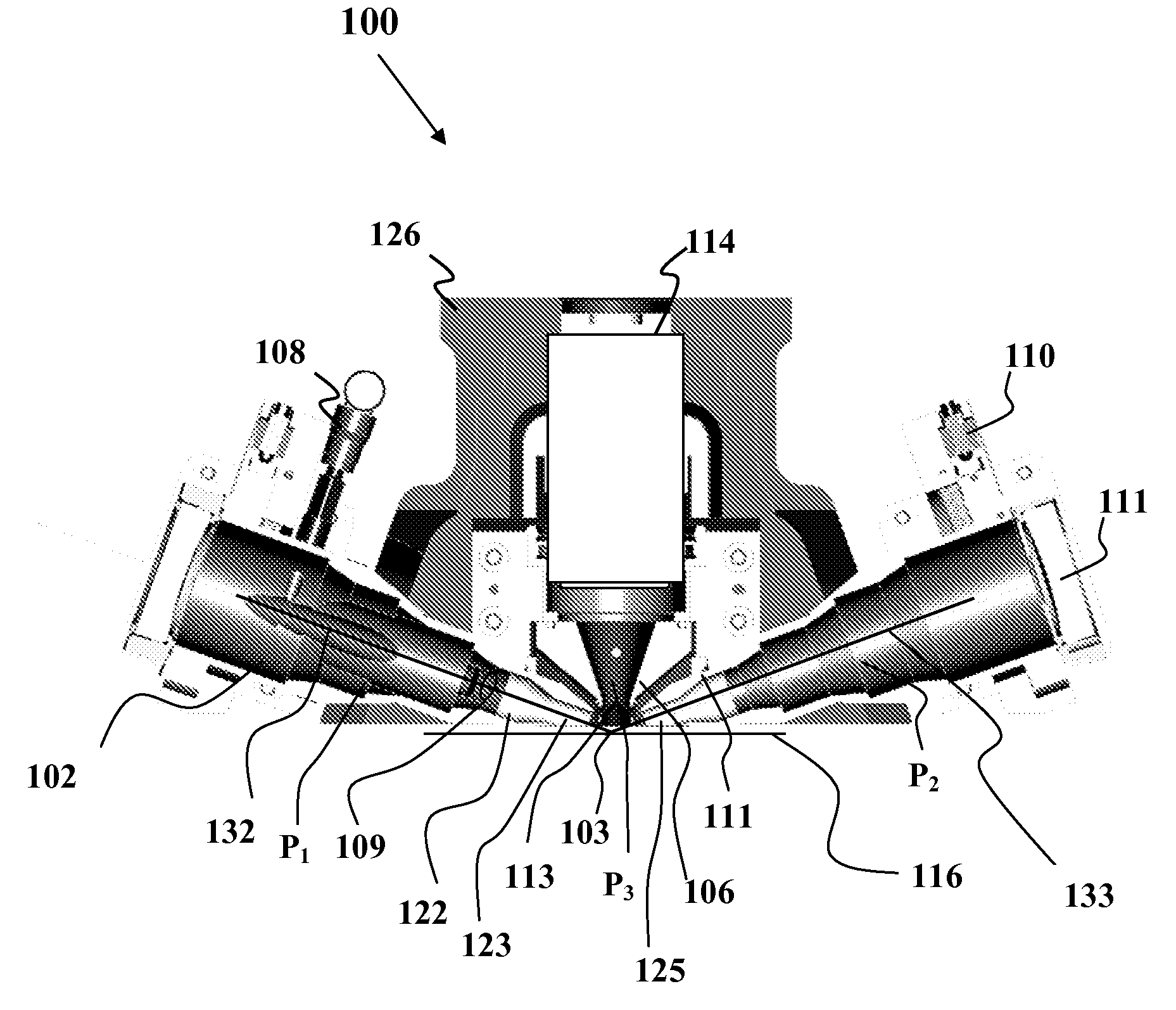
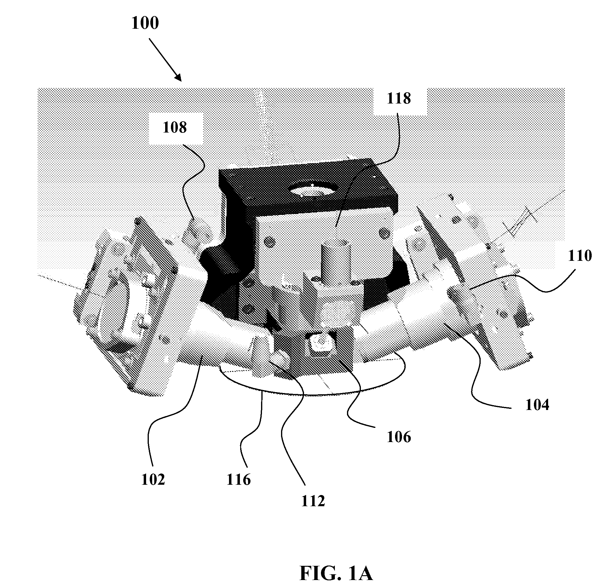
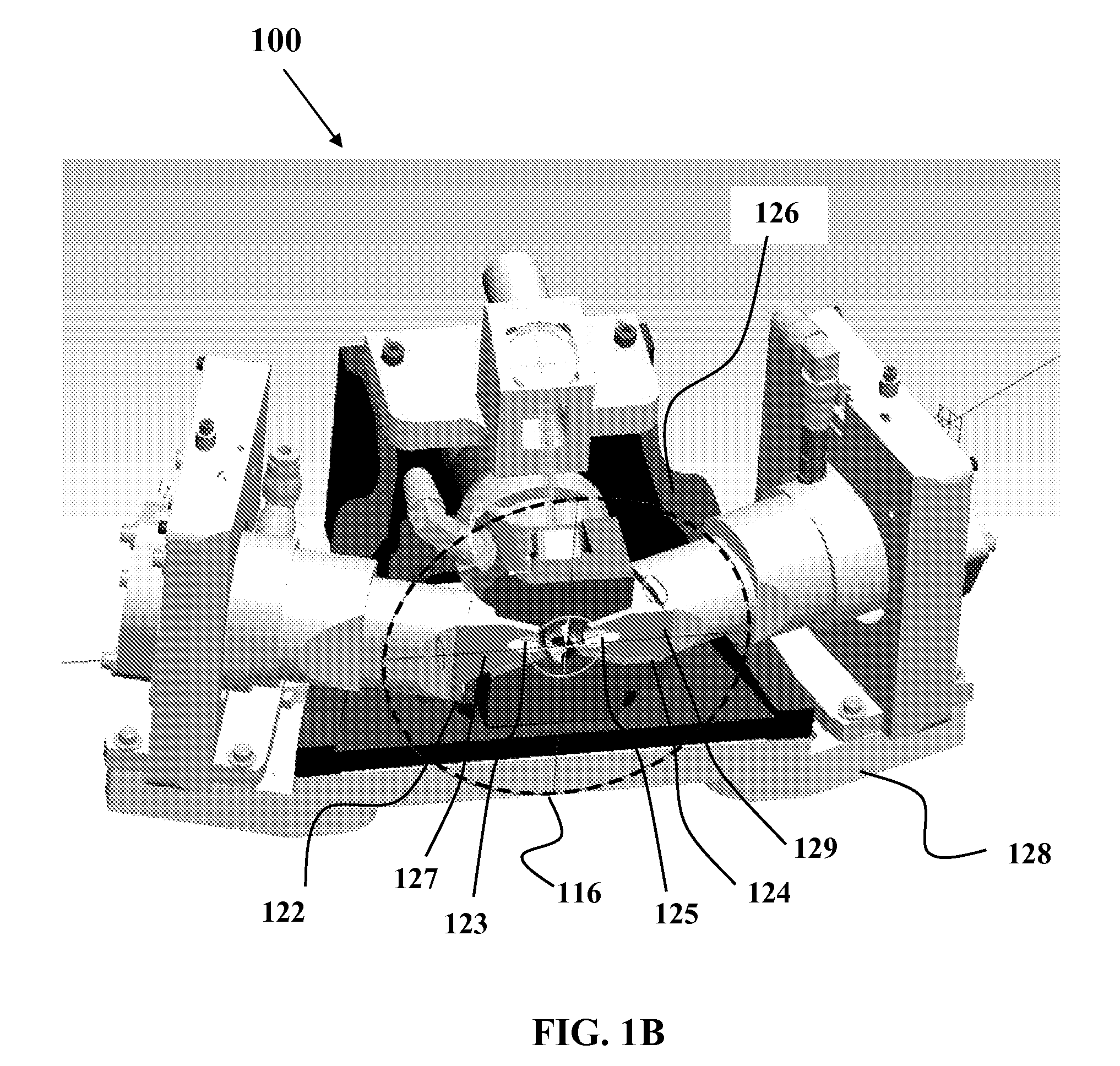
[0013]FIGS. 1A-1D illustrate a gas purge system 100 according to embodiments of the present invention. As shown in FIG. 1A, the gas purge system 100 may include an input beam optics housing 102, a collection optics housing 104 and a gas purge manifold 106. The gas purge system 100 also includes first, second and third gas inlets 108, 110 and 112, respectively. The first gas inlet 108 is located on input beam optics housing 102. The second gas inlet 110 is located on the collection optics housing 104. The third gas inlet 112 is located on the...
PUM
| Property | Measurement | Unit |
|---|---|---|
| flow rate | aaaaa | aaaaa |
| flow rate | aaaaa | aaaaa |
| length | aaaaa | aaaaa |
Abstract
Description
Claims
Application Information