Plastic skin forming process

a plastic skin and forming technology, applied in the field of plastic skin forming process, can solve the problems of limited mold shape, difficult maintenance of cleanliness, and large electroforming nickel tools that cannot be rotated in various axes, so as to reduce cycle time and any propensity to stress crack, reduce heat waste, and eliminate the effect of ducting and surrounding ambient area heating

Inactive Publication Date: 2008-09-16
INT AUTOMOTIVE COMPONENTS GRP NORTH AMERICA INC
View PDF51 Cites 0 Cited by
  • Summary
  • Abstract
  • Description
  • Claims
  • Application Information

AI Technical Summary

Benefits of technology

[0010]The present invention addresses the deficiencies of the prior art by providing an efficient skin-forming process utilizing lightweight molds heated via infrared (IR) energy and cooled through evaporation via a water / air mist spray. Since the IR energy is directed only at the backside of the mold surface utilizing heater elements that are contoured to match the mold, little heat is wasted and heating of ducting and the surrounding ambient area, is eliminated. Since the molds are not subjected to other stresses (air pressure, etc.) than their own weight, thinner and therefore, more uniform electroformed molds can be used, further decreasing cycle time and any propensity to stress crack. Evaporative cooling, using the latent heat of vaporization of water, yields a reduction in cooling time, which is also enhanced by the thinner more uniform electroform and the elimination of cooling duct work.

Problems solved by technology

The large electroformed nickel tools could not be rotated in various axes due to their size nor did they need to be, as the products were becoming long and relatively flat.
This conveyorized process also limited the number of shapes of molds that could be processed without facility modification to basically one as the heating apparatus were shape specific.
Cleanliness was difficult to maintain in this process as thicker sections of the plastic skin, particularly drips and runs from the excess liquid plastisol being dumped out, would remain unfused and transfer to both the station operator and adjacent shells.
The modular process resulted in the use of fewer molds and rapid mold changes.
A further difficulty with stainless steel tubes welded onto the electroform molds was one of shortened mold life.
The heat stresses that the nickel mold was exposed to during welding of the tubes to the mold resulted in mold cracking.
However, to move to the next level of cycle improvement, some of the disadvantages of this apparatus needed to be overcome.
The hot air impinging in the back of the electroformed mold was at such a pressure that the nickel mold would flex and ultimately crack due to fatigue.
The modular processing apparatus evolved to a large mold stand with a gas fired burner overhead and many feet of duct work supplying hot and cool air that were inefficiently heated and cooled.
Ambient noise and heat pollution became issues for the station operators.

Method used


Image

  • Plastic skin forming process
  • Plastic skin forming process
  • Plastic skin forming process

Examples


Embodiment Construction

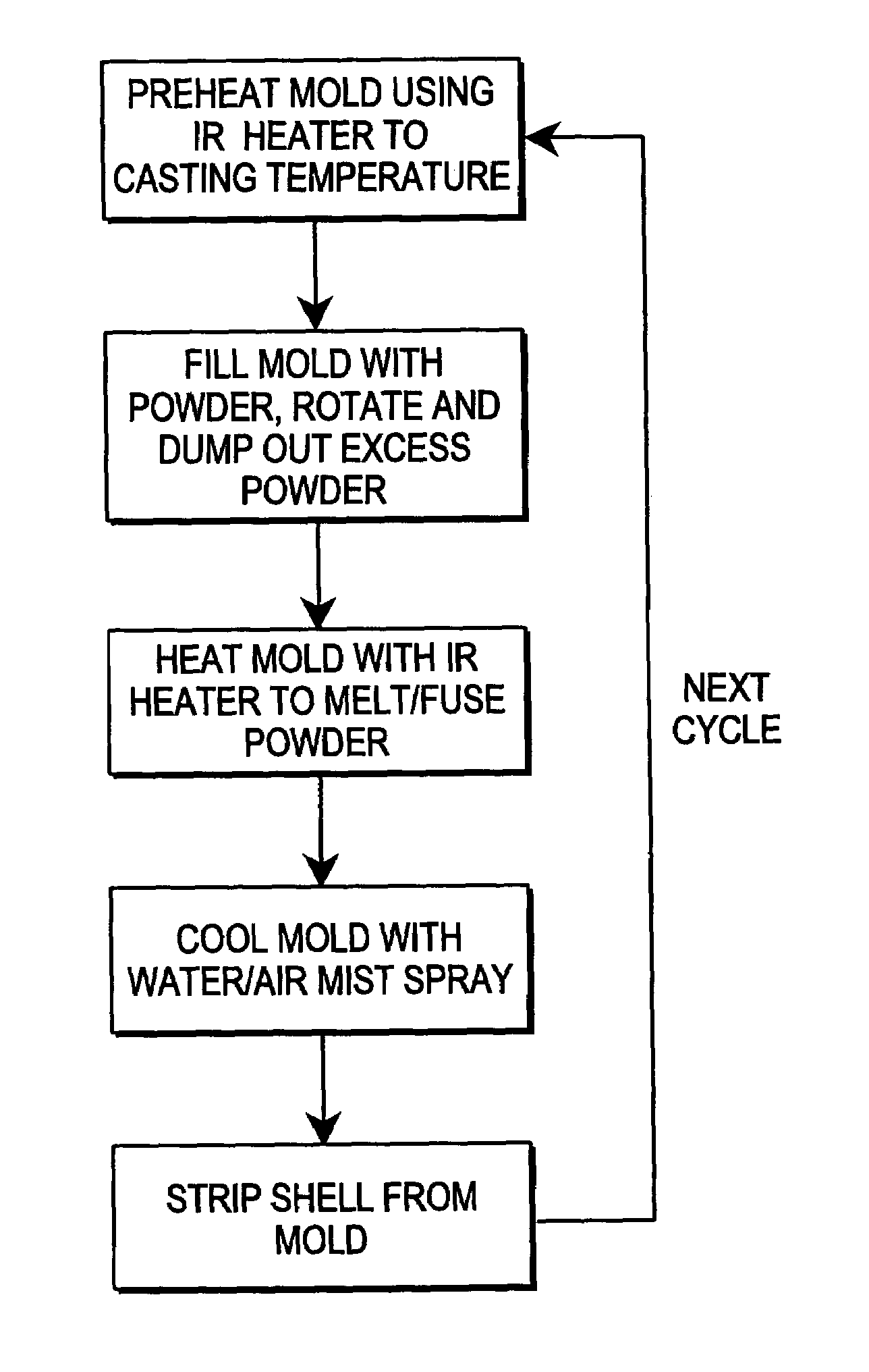
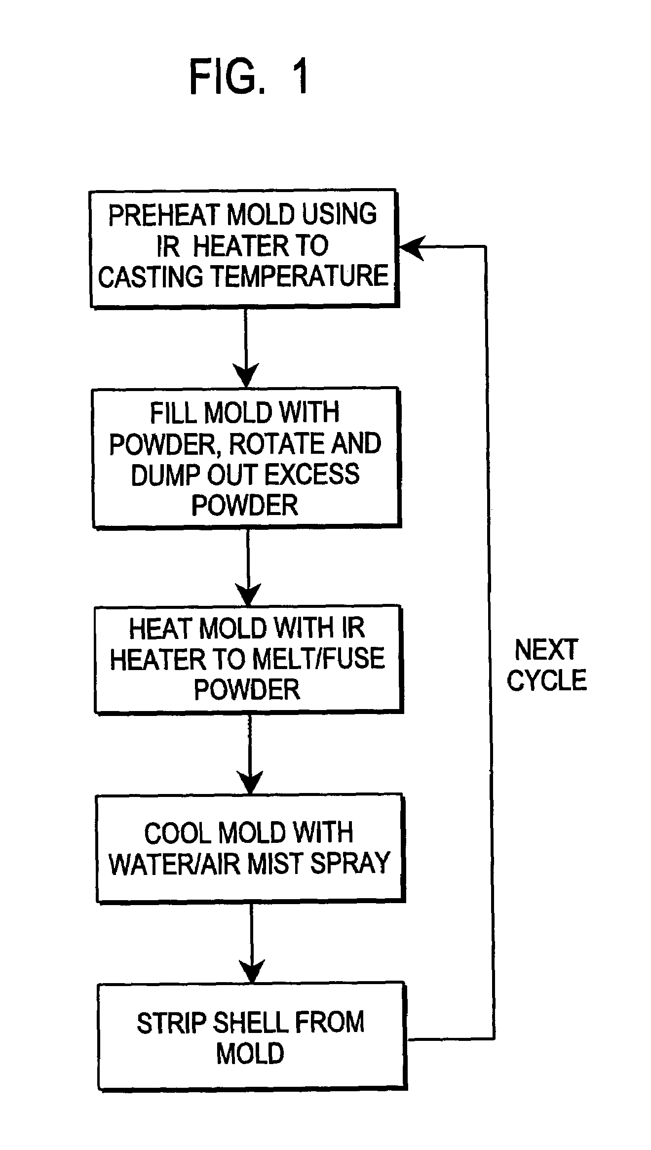
[0019]As noted above, FIG. 1 is a flow chart depicting the process steps used in the invention to produce plastic skins for automotive trim applications. A thin electroformed nickel mold is preheated using electric infrared heaters and when the mold reaches the preferred powder casting temperature for the specific plastic powder being processed, the mold is filled with powder, by using a powder box which clamps onto the mold face and when inverted fills the mold cavity with powder. The mold is then rotated generally around its major axis to allow the powder to contact the exposed heated inner surface of the electroformed mold and melt on this heated mold surface. Next the mold / powder box combination is inverted and any unmelted powder falls back into the powder box which is then unclamped and retracted. The mold is then sprayed with a fine mist of water and air to cool its surface to the desired stripping temperature. Once the stripping temperature is reached, the cooled solid skin ...


PUM

PropertyMeasurementUnit
emissivityaaaaaaaaaa
infrared energyaaaaaaaaaa

Abstract

An apparatus and method of producing plastic articles comprising preheating a metal mold (10) using infrared energy to establish a casting temperature, casting plastic material onto the preheated mold surface, fusing the plastic into a substantially uniform layer using infrared energy, cooling the metal mold using evaporative cooling, and removing the cast plastic article from said metal mold (10).

Description

CROSS REFERENCE TO RELATED APPLICATION[0001]This application is the National Stage of International Application No. PCT / US02 / 32413 filed Oct. 9, 2002 and published Apr. 17, 2003 as International Publication No. WO 03 / 031139, designating the United States, and which claims benefit of U.S. Provisional Application No. 60 / 327,979 filed Oct. 9, 2001.FIELD OF INVENTION[0002]The present invention relates to an improved method for forming relatively thin plastic skins or shells from a mold surface using infrared heating and evaporative cooling. More particularly, the method relates to the manufacture of thin thermoplastic shells or skins used as the outer surface for automotive interior trim products such as instrument panels, door panels, headrests, console covers, air bag doors, glove box doors and the like.BACKGROUND OF THE INVENTION[0003]Over many decades, the processes for forming thin skins of thermoplastic on a mold surface have evolved, driven primarily by cost and weight objectives...

Claims


Application Information

Patent Timeline
Patent Type & Authority Patents(United States)
IPC IPC(8): B29C35/02B29C35/16B29C67/06B29C39/04B29C33/34B29C33/06B29C33/38B29C33/56B29C35/08B29C41/08B29C41/18B29C41/38B29C41/46B29C45/14B29L31/58
CPCB29C33/56B29C41/08B29C41/46B29C45/14655B29C41/18B29C33/06B29C33/3828B29L2031/3005B29C2035/0822B29C2035/1691B29C48/12B29C48/13B29C48/904B29C48/911
Inventor GRIMMER, ROBERT A.SYPHERS, DAVEMOORE, DENIS
Owner INT AUTOMOTIVE COMPONENTS GRP NORTH AMERICA INC
Why Eureka
Try Eureka