Apparatus for directing plasma flow to coat internal passageways

a plasma flow and apparatus technology, applied in the field of deposition systems, can solve the problems of 316l stainless steel, generating particulates, scratching, etc., and achieve the effects of improving coating uniformity, high vacuum integrity, and less expensiv

Inactive Publication Date: 2008-11-04
SUB ONE TECH
View PDF21 Cites 50 Cited by
  • Summary
  • Abstract
  • Description
  • Claims
  • Application Information

AI Technical Summary

Benefits of technology

[0015]An advantage of the invention is that the coating apparatus allows a manufacturer to provide an end product which offers the benefits of a metallic exterior, such as corrosion resistance and high vacuum integrity, while allowing the use of a less expensive base material, such as a plastic. The metallic coating then serves as a functional, protective barrier to the base material. Another advantage of the invention is that an increase in coating uniformity can be achieved.
is that the coating apparatus allows a manufacturer to provide an end product which offers the benefits of a metallic exterior, such as corrosion resistance and high vacuum integrity, while allowing the use of a less expensive base material, such as a plastic. The metallic coating then serves as a functional, protective barrier to the base material. Another advantage of the invention is that an increase in coating uniformity can be achieved.

Problems solved by technology

Scratching is an issue, since it leads to the generation of particulates.
For example, 316L stainless steel, which is an austenitic alloy made of iron, chromium, nickel and other trace materials, does not intrinsically meet the 300 Vickers hardness requirement until the component is burnished.
Unfortunately, burnishing is time-intensive and significantly affects the yield of a manufacturing batch of the components.
However, other process reasons may dictate the use of LPCVD.
Coating a workpiece can be particularly problematic when the workpiece includes internal passages, such as those found in valves, pressure regulators, and tubes.
As the complexity of the geometry of the workpiece increases, there is a decrease in the ability to select a coating process on the basis of maximizing environmental and human safety.
While the Wesemeyer et al. patent and patents to Gorokhovsky (U.S. Pat. Nos. 5,435,900 and 6,663,755) describe coating apparatus that perform well in various applications, performance factors such as coating uniformity may be significantly affected when the workpiece is geometrically complex.

Method used


Image

  • Apparatus for directing plasma flow to coat internal passageways
  • Apparatus for directing plasma flow to coat internal passageways
  • Apparatus for directing plasma flow to coat internal passageways

Examples


second embodiment

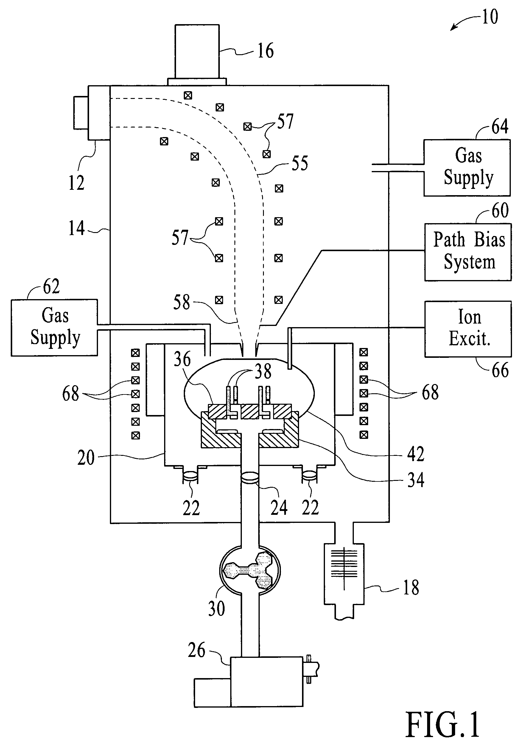
[0040]A second embodiment is shown in FIG. 5. In this embodiment, there are two source chambers 96 and 98 that supply a single deposition chamber 100. The two source chambers are identical. Each source chamber includes an anode 102, a cathode 104, a pumping arrangement 106 and a “necked down” region 108.

[0041]The passages from the source chambers 96 and 98 to the deposition chamber 100 are controlled by throttle valves 110 and 112. While not shown, the necked down regions 108 are preferably biased to prevent buildup of coating material. Another element of the pressure-control system is the throttle-controlled pumping arrangement 114 of the deposition chamber.

[0042]In FIG. 5, the deposition chamber 100 is connected to an ion excitation system 116 and to a gas source 118. As described above, the ionization excitation system may be a microwave source or a plasma source, such as one that utilizes ECR, distributed ECR, or RF techniques. The gas source 118 may provide an inert gas, such a...

third embodiment

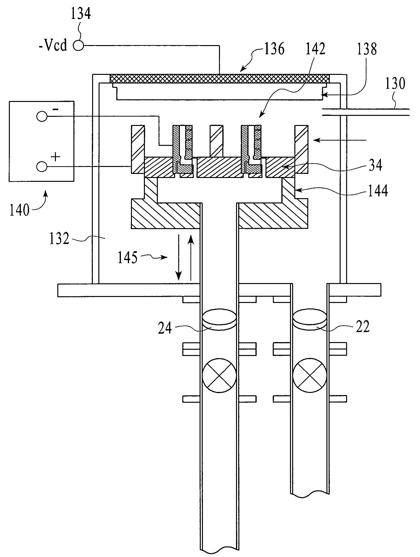
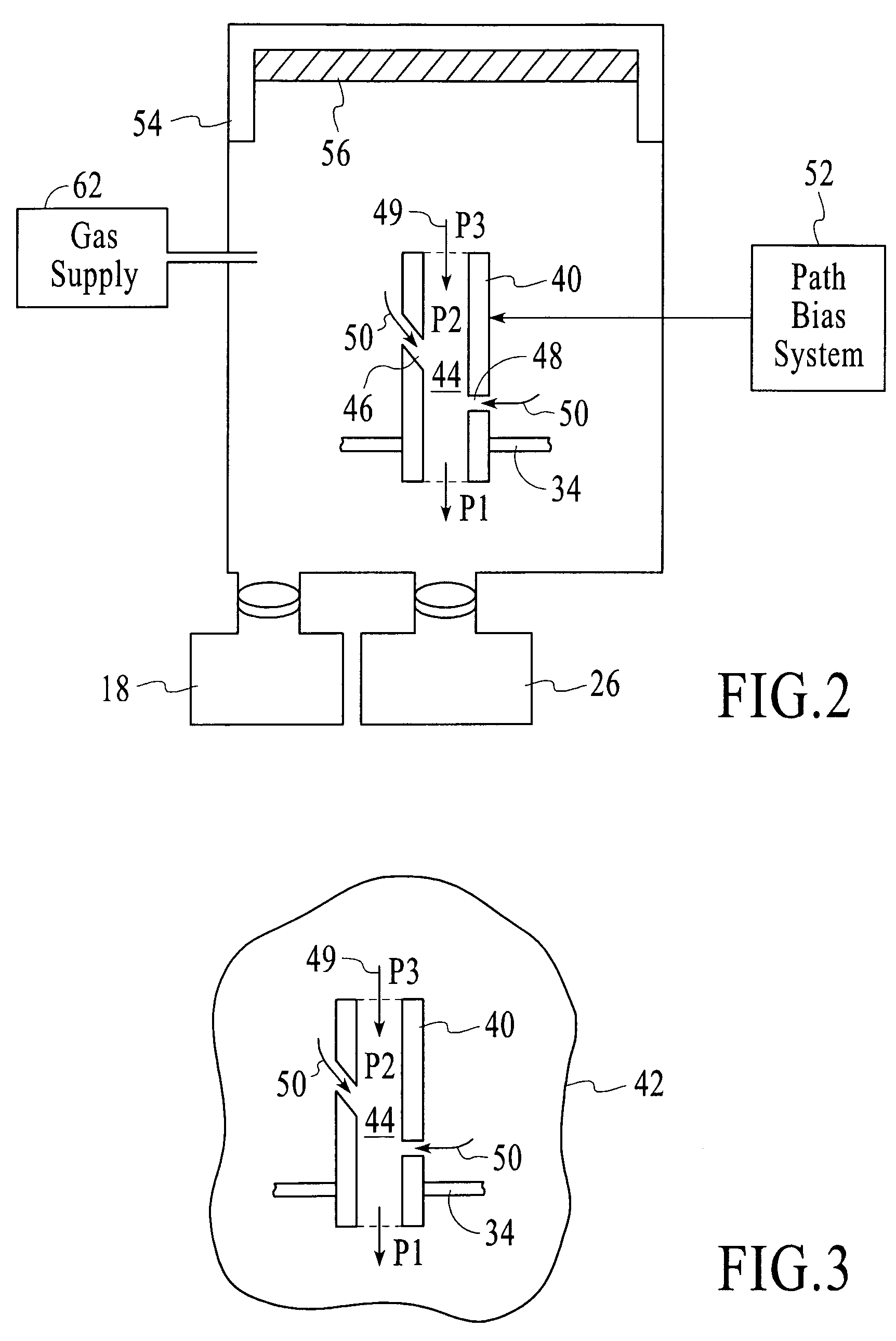
[0045]the invention is shown in FIG. 6. This embodiment utilizes a PVD method capable of operating at higher pressures (20 mTorr to 1 Torr), such as diode sputtering. As a consequence, only a single chamber is required, thereby providing a simplification as compared to the previously described embodiments. As before, an inert or reactive background gas can be introduced via a gas manifold inlet 130. The introduction of background gas is intended to bring the deposition chamber 132 to the required pressure for continuum flow and the effective use of the flow-through technique. The workpiece support member 34 and the throttle valves 22 and 24 are functionally identical to those of the embodiment of FIG. 1, so that the same reference numerals are employed. The workpiece support member is formed of an insulator material and is configured to ensure that the flow is through the workpiece. The adjustments of the throttle valves 22 and 24 and the adjustment of the flow rate of background ga...


PUM

PropertyMeasurementUnit
pressuresaaaaaaaaaa
pressuresaaaaaaaaaa
pressuresaaaaaaaaaa

Abstract

An apparatus for coating surfaces of a workpiece is configured to establish a pressure gradient within internal passageways through the workpiece, so that the coating within the internal passageways exhibits intended characteristics, such as those relating to smoothness or hardness. The coating apparatus may include any or all of a number of cooperative systems, including a plasma generation system, a manipulable workpiece support system, an ionization excitation system configured to increase ionization within or around the workpiece, a biasing system for applying a selected voltage pattern to the workpiece, and a two-chamber system that enables the plasma generation to take place at a first selected pressure and the deposition to occur at a second selected pressure.

Description

TECHNICAL FIELD[0001]The invention relates generally to deposition systems and more particularly to apparatus for coating internal passageways of a workpiece.BACKGROUND ART[0002]During the design and manufacture of components of systems that are to be used within particular industries, important concerns include surface smoothness, hardness, cost and environmental effects of fabrication techniques. As one example, the semiconductor fabrication industry utilizes ultra high purity gas delivery systems in which these concerns are considered in the selection of techniques for manufacturing the system components. Such system components include mass flow controllers, valves, pressure regulators, purifiers, filters and tubing. In the semiconductor industry, corrosion resistance in a gas delivery system is critical to achieving and maintaining a contaminant-free environment. Smoothness plays an important role in controlling turbulence and minimizing moisture-inducing conditions. There are d...

Claims


Application Information

Patent Timeline
Patent Type & Authority Patents(United States)
IPC IPC(8): C23C16/455C23C14/34C23C14/35C23C16/503C23C16/509C23C16/517C23C16/511C23C16/505C23C16/50C23C14/46C23C14/50C23C14/04C23C14/32C23C16/00
CPCC23C14/046C23C14/325C23C14/50H01J37/32357
Inventor BOARDMAN, WILLIAM JOHNMERCADO, RAUL DONATETUDHOPE, ANDREW WILLIAM
Owner SUB ONE TECH
Why Eureka
Try Eureka