

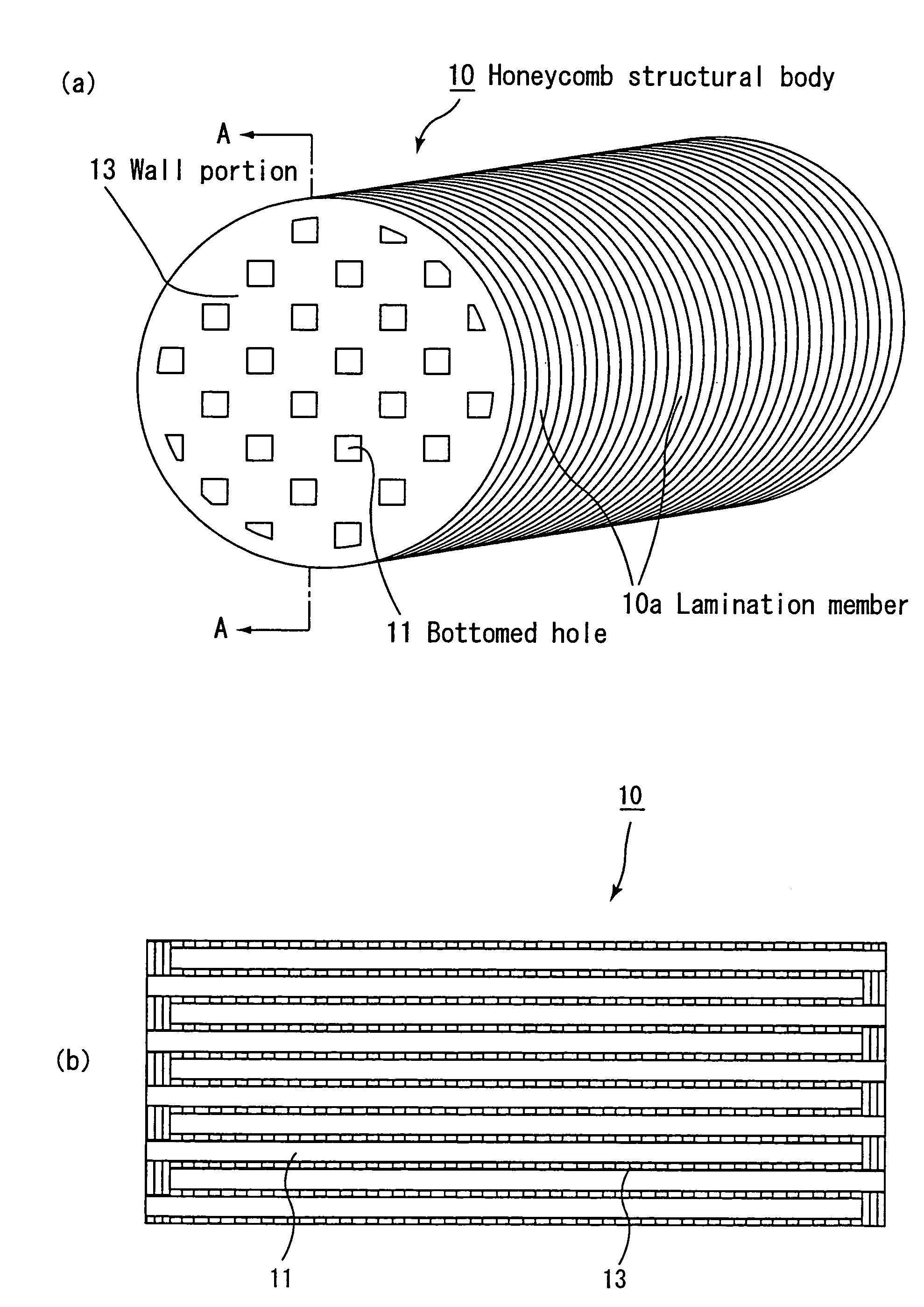
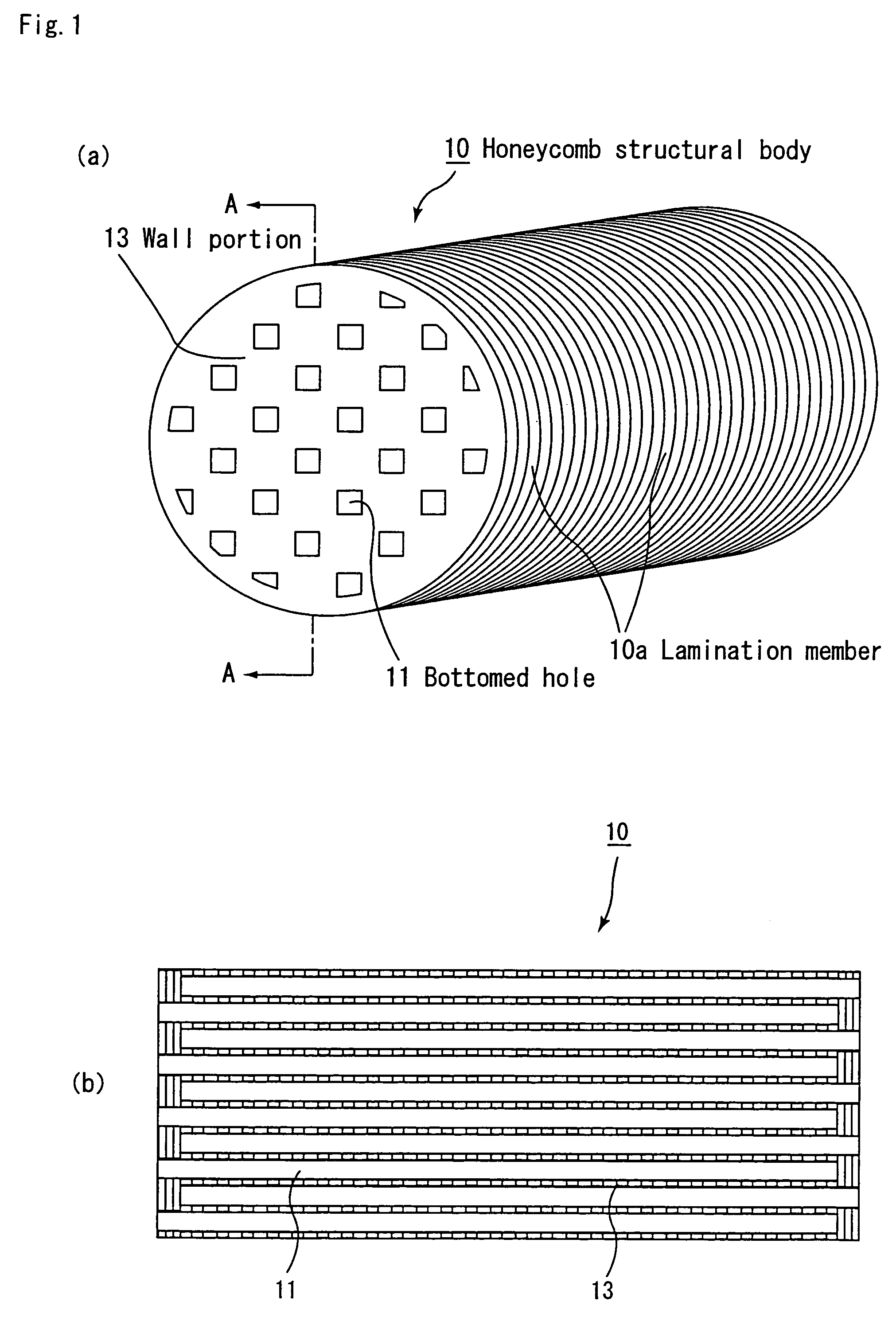
Honeycomb structural body
a technology of honeycomb and structural body, applied in the direction of catalyst activation/preparation, metal/metal-oxide/metal-hydroxide catalyst, machine/engine, etc., can solve the problems of reducing the pressure loss after particulate collection, and affecting the collection efficiency. , to achieve the effect of improving the collection efficiency, weakening to the thermal stress, and improving the collection efficiency
- Summary
- Abstract
- Description
- Claims
- Application Information
AI Technical Summary
Benefits of technology
Problems solved by technology
Method used
Image

Examples
example 1
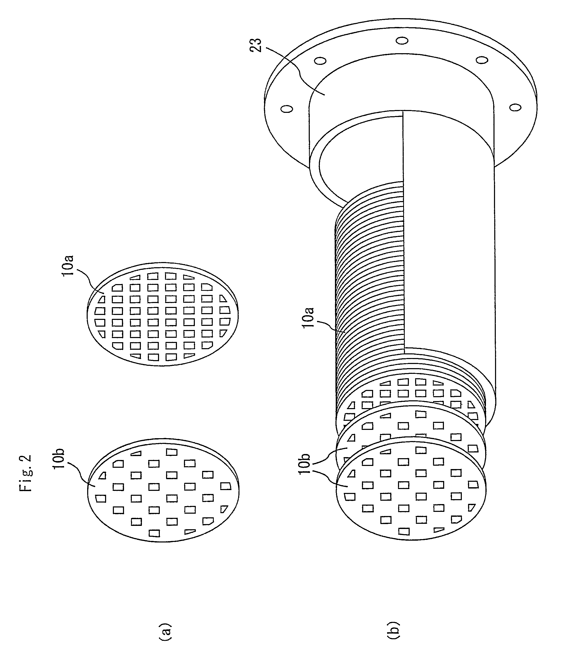
(1) Manufacturing Process of Lamination Members
[0145]A three-dimensional mesh-shape porous member, made of Ni—Cr alloy (trade name: CELMET, average pore diameter: 400 μm, made by Sumitomo Electric Industries Ltd.), was compressed by a roller so as to have an average pore diameter of 80 μm, and after having been machined into a disc shape having a size of 43.8 mm in diameter×1 mm in thickness, the resulting disc is machined by laser to form holes, each having a size of 6 mm×6 mm, over the almost entire surface with mutual intervals of 2 mm; thus, a lamination member A1 having a honeycomb shape was manufactured.
[0146]Moreover, in order to form members for use in two end portions of the honeycomb structural body, a three-dimensional mesh-shape porous member, made of Ni—Cr alloy (trade name: CELMET, average pore diameter: 400 μm, made by Sumitomo Electric Industries Ltd.), was compressed by a roller so as to have an average pore diameter of 80 μm, and after having been machined into a d...
example 2
[0151]A three-dimensional mesh-shape porous member, made of Ni—Cr alloy (trade name: CELMET, average pore diameter: 400 μm, made by Sumitomo Electric Industries Ltd.), was compressed by a roller so as to have an average pore diameter of 80 μm, and after having been machined into a disc shape having a size of 143.8 mm in diameter×1 mm in thickness, the resulting disc is machined by laser to manufacture a lamination member A2 having a honeycomb shape with a thickness of 2 mm in the same manner as the lamination member A1; then, the same processes as Example 1 were carried out except that after having applied a catalyst thereto, five of the lamination members B1, 70 of the lamination members A2 and five of the lamination members B1 were laminated in this order so that an exhaust gas purifying device in which a honeycomb structural body having a length of 150 mm was assembled into a casing was prepared.
example 3
[0152]A three-dimensional mesh-shape porous member, made of Ni—Cr alloy (trade name: CELMET, average pore diameter: 400 μm, made by Sumitomo Electric Industries Ltd.), was compressed by a roller so as to have an average pore diameter of 80 μm, and after having been machined into a disc shape having a size of 143.8 mm in diameter×4 mm in thickness, the resulting disc is machined by laser to manufacture a lamination member A3 having a honeycomb shape with a thickness of 4 mm in the same manner as the lamination member A1; then, the same processes as Example 1 were carried out except that after having applied a catalyst thereto, five of the lamination members B1, 35 of the lamination members A3 and five of the lamination members B1 were laminated in this order so that an exhaust gas purifying device in which a honeycomb structural body having a length of 150 mm was assembled into a casing was prepared.
PUM
| Property | Measurement | Unit |
|---|---|---|
| pore diameter | aaaaa | aaaaa |
| pore diameter | aaaaa | aaaaa |
| thickness | aaaaa | aaaaa |
Abstract
Description
Claims
Application Information