All fiber chirped pulse amplification system and method

a chirped pulse and amplification system technology, applied in the field of optical pulse amplification systems, can solve the problems of limiting the ultimately achievable amplified power/energy of the same amplifier design, reducing the peak optical power of the same pulse energy, and reducing the loss at said optical connections. , to achieve the effect of reducing losses and minimizing nonlinear distortion

Inactive Publication Date: 2009-02-03
CORNING INC
View PDF8 Cites 23 Cited by
  • Summary
  • Abstract
  • Description
  • Claims
  • Application Information

AI Technical Summary

Benefits of technology

[0008]The photonic bandgap fiber may be gas filled, or evacuated in order to minimize nonlinear distortion. The photonic bandgap fiber and the dispersion compensating optical fiber are preferably fusion spliced to an output end and input end, respectively, of the optical fiber amplifier to reduce losses at said optical connections. The fiber amplifier preferably includes fiber doped with a rare earth element such as erbium or ytterbium and has normal dispersion to avoid a soliton effect in the amplifier.

Problems solved by technology

Stretching greatly reduces peak optical power for the same pulse energy.
Unfortunately, existing bulk optics compressors are typically very bulky, with a physical length of 1 meter or more.
However, the potential advantages have been only partially recognized by such prior art designs as either the compressed pulse width could not be reduced below 1 picosecond, or the stretching ratio of the pulses entering the amplifier did not exceed 40 times (which would limit ultimately achievable amplified power / energy for the same amplifier design).
Further compression of the pulse width by the PBGF or stretching by the dispersion compensating fiber used in this device results in unacceptably high degrees of pulse distortion due to the difficulty of matching the relatively high dispersion slope of the PBGF with the opposite dispersion slope of the dispersion compensating fiber.
However, this system is not free of disadvantages.
First, group delay ripple of the CFBGs can easily exceed several picoseconds, introducing distortion that can not be compensated.
Second, exact compensation might require multiple CFBGs with multiple independently tunable segments each, greatly increasing complexity and cost of the overall system.

Method used


Image

  • All fiber chirped pulse amplification system and method
  • All fiber chirped pulse amplification system and method
  • All fiber chirped pulse amplification system and method

Examples


Embodiment Construction

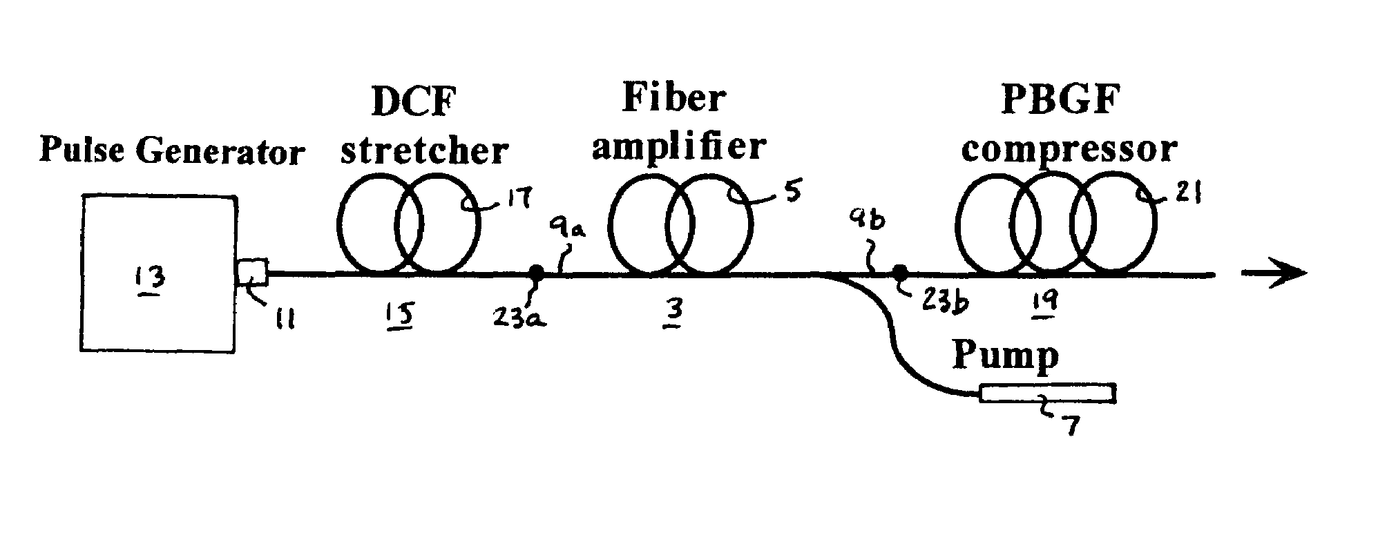
[0023]With reference now to FIG. 1, the all-fiber chirped pulse amplification (CPA) system 1 of the invention comprises a fiber amplifier 3 including a segment 5 of fiber doped with a rare earth metal such as erbium or ytterbium coupled to a light pump 7 which is typically a laser that generates light at the excitation frequency of the dopant atoms in the segment 5. The fiber amplifier has an input 9a and an output 9b as shown. While not expressly shown in the diagram, the fiber amplifier 3 may include a pre-amplifier serially connected to a power amplifier, and is preferably of a double-clad design that allows for a high power output. The fiber amplifier 3, per se, does not constitute the invention and any number of prior art designs may be used to implement the system and method of the invention.

[0024]A pulse generator 13 is optically connected to a pulse stretcher 15. The pulse generator 13 may be a mode-locked fiber laser that generates pulses with energy on the order of 1 nanoj...


PUM


Abstract

An all-fiber chirped pulse amplification (CPA) system and method is provided that utilizes a hollow core photonic bandgap fiber as a pulse compressor and a dispersion compensating optical fiber as a pulse stretcher that are matched with respect to both the amount and slope of dispersion to avoid peak power-limiting pulse distortion. The CPA system includes a rare earth ion-doped optical fiber amplifier having an input and an output that amplifies optical pulses having a center wavelength of λc, a pulse compressing length L1 of hollow core photonic bandgap fiber having a dispersion value D1 and a dispersion slope S1 that varies over a wavelength λ of the pulses that is optically connected to the output of the fiber amplifier and having a k-parameter defined by a ratio of D1 over the slope of the function D1(λ) that is larger than about 50, and a pulse stretching length L2 of dispersion compensating optical fiber connected to the input of the fiber amplifier having a dispersion value D2 and dispersion slope S2. The lengths are selected such that L1D1=−L2D2, and the center wavelength λc of the inputted optical pulses is preferably close to the center wavelength of the bandgap of the photonic bandgap fiber.

Description

FIELD OF THE INVENTION[0001]This invention generally relates to optical pulse amplification systems, and is specifically concerned with an all fiber chirped pulse amplification system and method that uses photonic bandgap fiber as a pulse compressor.BACKGROUND OF THE INVENTION[0002]Chirped pulse amplification (CPA) is a technique allowing amplification of ultra-short light pulses to a very high energy / power level in a solid state amplifier. To avoid pulse distortion or break up due to the optical nonlinearity of the amplification medium, the pulse is stretched (typically by at least several hundred times) by passing it through a strongly dispersive element and thereby “chirping” it, or delaying its spectral components in respect to each other. Stretching greatly reduces peak optical power for the same pulse energy. After amplification, the pulse is compressed back to its original duration. Such pulse compression is typically accomplished using bulk optics (prisms and / or gratings) fo...

Claims


Application Information

Patent Timeline
Patent Type & Authority Patents(United States)
IPC IPC(8): H01S4/00
CPCH01S3/0057H01S3/06754H01S3/2308G02B6/02304H01S3/06712H01S3/06725
Inventor KUKSENKOV, DMITRI VLADISLAVOVICHLI, SHENPING
Owner CORNING INC
Why Eureka
Try Eureka