Variable intake valve and exhaust valve timing strategy for improving performance in a hydrogen fueled engine

a technology of hydrogen fueled internal combustion engine and timing strategy, which is applied in the direction of machines/engines, non-mechanical valves, transportation and packaging, etc., can solve the problems of increasing the propensity of fuel to backfire, pre-ignition, and/or backlash, reducing engine output, and reducing so as to reduce the effect of exhaust emissions and increasing fuel renewability and transferability

Inactive Publication Date: 2009-02-10
FORD GLOBAL TECH LLC
View PDF18 Cites 12 Cited by
  • Summary
  • Abstract
  • Description
  • Claims
  • Application Information

AI Technical Summary

Benefits of technology

[0002]An engine may burn gaseous fuels such as hydrogen (H2), natural gas, lighter flammable hydrocarbon derivatives, etc. Using gaseous fuel in an internal combustion engine can provide various advantages compared to liquid fuel injection. Examples of such advantages may include reduction of exhaust emissions of nitrogen oxides, particulate matter, and hydrocarbons as well as increased fuel renewability and transferability.
[0003]In the example of hydrogen fueled engines, the hydrogen may be exposed to hot residual gases as well as heated engine components, such as the intake manifold. The gas may also be exposed to heat from the cylinder head porting, piston, valves, and walls of a combustion chamber during the intake stroke. This exposure can increase a propensity of the fuel to backfire, pre-ignite, and / or backflash, as well as reduce engine output. Further, such effects can be exacerbated if the hydrogen injection duration is extended.
[0005]However, the inventors herein have recognized that backfiring, pre-ignition, and backflash may still occur. For example, injected hydrogen may be exposed to hot combustion chamber surfaces because the hydrogen is injected at top dead center immediately after the completion of an exhaust stroke. Further, a propensity of combustion anomalies such as backfiring, pre-ignition, and / or backflash may increase when the heated hydrogen is mixed with heated boosted air inducted into the combustion chamber.
[0007]In this way, engine efficiency may be improved by reducing backfiring, pre-ignition, and backflash. For example, in one embodiment, under conditions when backfiring, pre-ignition and / or backflash are more likely (e.g. high temperature), intake valve opening can be retarded to provide additional time before the hydrogen and / or air is inducted into the cylinder. This allows metal surfaces of the combustion chamber including the head porting more time to cool. Additionally, after the exhaust valve closes and before the intake valve opens, the downward piston motion of the intake stroke expands the combustion chamber content until the intake valve opens. This expansion may result in lower gas pressure and temperature, and thus a cooler environment for the hydrogen / air mixture to enter when the intake valve finally opens. However, under conditions where such cooling is not needed, intake valve opening may be less retarded or may be kept near the top dead center thereby to reduce any pumping losses.
[0008]Further, any reduction in torque and power due to volumetric efficiency by the late intake valve opening (and potentially late intake valve closing) can be compensated by the boosting of the intake air.
[0010]Again, such operation can provide various advantages. For example, at low engine speed, the late intake valve opening and the early exhaust valve closing may increase fuel efficiency compared with varying the intake valve timing alone. At high engine speed, the late intake valve opening and the late exhaust valve closing may also reduce a tendency for combustion anomalies by reducing exhaust residuals.

Problems solved by technology

This exposure can increase a propensity of the fuel to backfire, pre-ignite, and / or backflash, as well as reduce engine output.
However, the inventors herein have recognized that backfiring, pre-ignition, and backflash may still occur.
Further, a propensity of combustion anomalies such as backfiring, pre-ignition, and / or backflash may increase when the heated hydrogen is mixed with heated boosted air inducted into the combustion chamber.

Method used


Image

  • Variable intake valve and exhaust valve timing strategy for improving performance in a hydrogen fueled engine
  • Variable intake valve and exhaust valve timing strategy for improving performance in a hydrogen fueled engine
  • Variable intake valve and exhaust valve timing strategy for improving performance in a hydrogen fueled engine

Examples


Embodiment Construction

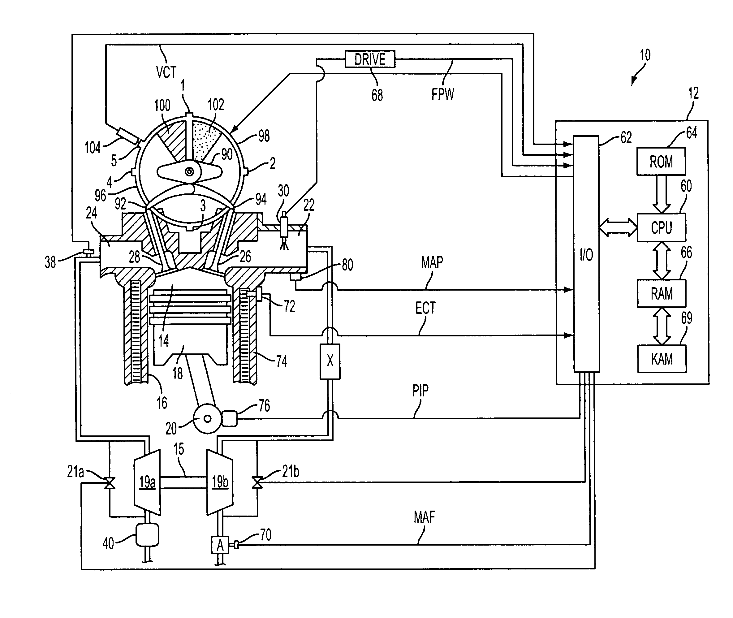
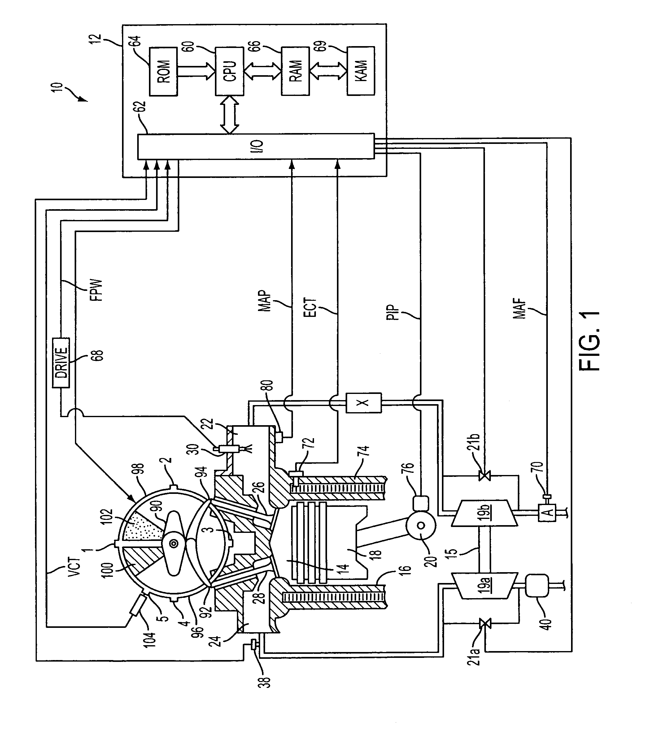
[0016]FIG. 1 shows, generally at 10, an exemplary embodiment of one cylinder of a multi-cylinder engine, intake and exhaust paths connected to that cylinder, and an exemplary embodiment of a camshaft having a variable timing mechanism for controlling the valves of the cylinder. It will be appreciated that the configuration of engine 10 is merely exemplary, and that the systems and methods described herein may be implemented in any other suitable engine. Further, the engine may be spark ignited via a spark plug located in the cylinder (not shown), the timing of which may be varied with operating conditions. While this example shows a system for varying intake and exhaust timing, in practice, separate systems may be used. For example, one system is used for adjusting intake valve timing (opening and / or closing) and another for adjusting exhaust valve timing (opening and / or closing). Further, additional adjustment may be used, such as variable valve lift, if desired.

[0017]Continuing wi...


PUM


Abstract

A method for a hydrogen fueled internal combustion engine to reduce backfiring, pre-ignition, and / or backflash, the engine also including a combustion chamber, an intake manifold, an exhaust manifold, at least one intake valve, at least one exhaust valve, a hydrogen injector, a compression device, and a variable valve timing system coupled to the intake valves. The method comprises compressing air using the compression device; injecting hydrogen and mixing at least said hydrogen with air discharged from the compression device; and opening the intake valve to induct at least air into the combustion chamber, wherein the intake valve opening time varies with an operating condition.

Description

FIELD[0001]The present application relates generally to a system and method for reducing backfire, pre-ignition, and / or backflash in a hydrogen fueled internal combustion engine, and more specifically to a system and method that varies the intake valve timing and / or exhaust valve timing to reduce backfire, pre-ignition and / or backflash.BACKGROUND AND SUMMARY[0002]An engine may burn gaseous fuels such as hydrogen (H2), natural gas, lighter flammable hydrocarbon derivatives, etc. Using gaseous fuel in an internal combustion engine can provide various advantages compared to liquid fuel injection. Examples of such advantages may include reduction of exhaust emissions of nitrogen oxides, particulate matter, and hydrocarbons as well as increased fuel renewability and transferability.[0003]In the example of hydrogen fueled engines, the hydrogen may be exposed to hot residual gases as well as heated engine components, such as the intake manifold. The gas may also be exposed to heat from the...

Claims


Application Information

Patent Timeline
Patent Type & Authority Patents(United States)
IPC IPC(8): F02B43/00F01L1/34F02B33/00F02B75/02
CPCF02B37/00F01L9/04Y02T10/144Y10S123/13Y02T10/12F01L9/20
Inventor LEONE, THOMASBOYER, BRADSTOCKHAUSEN, WILLIAM
Owner FORD GLOBAL TECH LLC
Why Eureka
Try Eureka