Container for evaporation of metal and method to manufacture thereof

a technology for evaporating containers and metals, applied in the direction of manufacturing converters, separation processes, furnaces, etc., can solve the problems of reducing the life of metallization boats, slag begins to accumulate around the edge of the metal puddle in the boat, and the life of the boats is further reduced, so as to prolong the service life of refractory boats

Inactive Publication Date: 2009-02-24
GENERAL ELECTRIC CO
View PDF20 Cites 4 Cited by
  • Summary
  • Abstract
  • Description
  • Claims
  • Application Information

AI Technical Summary

Benefits of technology

[0009]The invention relates to a refractory container for evaporating metals having an evaporation surface in contact with molten metal with a direction of conduction parallel to a length axis of the refractory boat and a plurality of grooves in the evaporation surface, with the grooves each having at least one of a depth of at least 1.2 mm, a width of at least 1.75 mm, and an interval spacing of at least 2.2 mm, and with at least two of the plurality of grooves having at least a portion of length at an angle of 10 to 170° to the direction of conduction of the refractory boat.

Problems solved by technology

This means that the metal melt will be much more aggressive and behave as a corrosive acid, lowering the life of the metallization boats.
Additionally, when the operation is carried out with repetitive heating, cooling, and exposure to molten metals during that span, the life of the boats is further reduced.
After a few hours in operation, a slag begins to build up around the edge of the metal puddle in the boat.
It inhibits the spreading of the metal puddle, thus increases the operating temperature and further reduces the useful life of the boat.
During metallization, the molten aluminum corrodes the surface of the boat, typically resulting in deep grooves running from the anterior to the posterior of the boat and penetrating into the boat's depth.
These grooves over time, effect the spreading of the aluminum melt, affecting the deposition uniformity on the metallized substrate.
Additionally, the grooves can cause the spattering of the liquid aluminum due to excessive accumulation of the aluminum in the grooves.
Therefore, minimizing the depth of grooves, or slowing the formation of grooves over the evaporation surface can lead to longer useful boat life.

Method used


Image

  • Container for evaporation of metal and method to manufacture thereof
  • Container for evaporation of metal and method to manufacture thereof
  • Container for evaporation of metal and method to manufacture thereof

Examples


examples 1-4

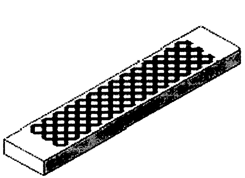
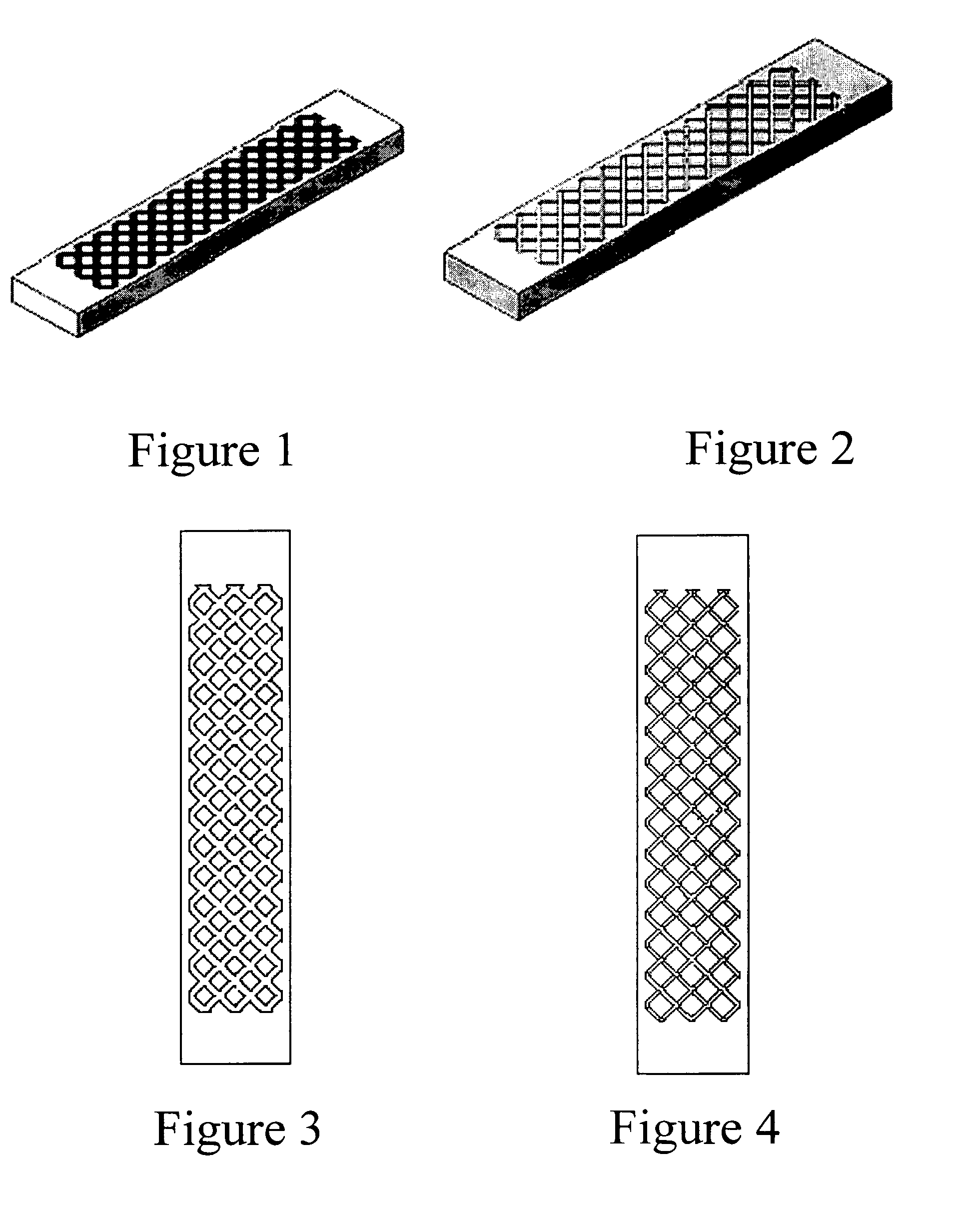
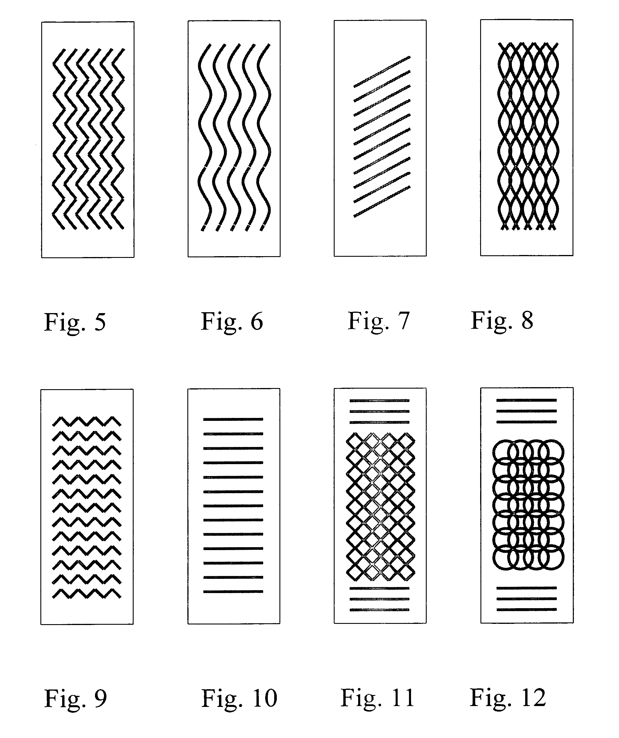
[0052]In all examples, evaporator boats commercially available from GE Advanced Ceramics of Strongsville, Ohio, under the trade name “VaporStar” were used. The boats were machined for an overall dimensions of 30 mm wide, 10 mm thick, and 150 mm long. Grooves of various dimensions were machined on the surface of the boats such that the grooves were at 45 degrees to the longitudinal axis of the boat, creating an interconnected pattern. The grooves were machined using a sandblasting technique, for the following dimensions for the grooves.

[0053]

TABLE 1Initial boatGroovethicknessWidthGroove DepthGroove SpacingExample(mm)(mm)(mm)(mm)SM-110.20.50.11.0SM-210.21.00.62.0SM-310.02.01.54.0SM-410.21.00.95.0

[0054]FIGS. 1-2 are perspective views and FIGS. 3-4 are top views of the boats of the invention in Examples 3-4. Examples 1 and 2 are comparative examples illustrating the grooved boats of the prior art. FIGS. 24(a)-27(a) are photographs of the top views of the grooved sections of the boats in...

examples 5-8

[0060]In these examples, evaporator boats commercially available from GE Advanced Ceramics of Strongsville, Ohio, under the trade name “VaporStar” were also used. The boats were machined for an overall dimensions of 10 mm×40 mm×132 mm.

[0061]The top surface of the boats in FIGS. 29(a), 30(a), and 31(a) were wet-sanded with 320 grit sand paper. The top surface of the boat of FIG. 28(a) was ground with a standard grinding wheel to generate a 0.25 mm deep ground cavity. Grooves of about 1 mm wide, 1 mm deep, and about 4 mm apart were manually machined in the top surface of the boat of FIG. 30(a) using a Dremel tool to create intersecting patterns of an approximate 45° angle to the electrical conduction direction. Grooves were manually machined in the top surface of the boat of FIG. 31(a) using a Dremel tool to create a groove pattern of the prior art, having longitudinal grooves of about 1 mm deep, 1 mm wide, and 3 mm apart.

[0062]The boats were tested under the same aluminum metallizati...

example 9

[0063]An evaporator boat commercially available from GE Advanced Ceramics of Strongsville, Ohio, under the trade name “VaporStar” was used. The boat was machined for an overall dimensions of 10.2 mm thickness×40 mm×132 mm with grooves having dimensions identical to the boat of Example 4, i.e., 1 mm thickness, 0.9 depth, and 5 mm spacing. The boat surface, including the evaporation surface in contact with molten metal and the grooves, was coated with a boron nitride (BN) paint. BN coating paint is commercially available from sources including General Electric Company of Strongsville, Ohio and Zyp Coatings, Inc. of Oak Ridge, Tenn. (e.g., a water based BN from GE, or BN Lubricoat® Blue from Zyp).

[0064]The boat was tested under the same aluminum metallization condition similar to that of Example 4. The boat held up quite well with minimal and more uniform grooving even compared with the boat of Example 4 after 8 hours. The test continued for a total of 17 hours, showing that the coatin...


PUM

PropertyMeasurementUnit
depthaaaaaaaaaa
widthaaaaaaaaaa
widthaaaaaaaaaa

Abstract

A refractory container for evaporating metals, having improved useful life and corrosion resistance properties, the evaporation surface of the container having a plurality of grooves formed at the bottom surface. The grooves have either a depth of at least 1.2 mm, a width of at least 1.75 mm, or an interval spacing of at least 2.2 mm between adjacent grooves (or centers of adjacent grooves), and combinations thereof.

Description

FIELD OF THE INVENTION[0001]The present invention relates to an improved container for the vacuum evaporation of metal.BACKGROUND OF THE INVENTION[0002]Vacuum deposition is a common method for coating metals such as aluminum, copper, zinc, and tin onto various substrates of metal, glass, and plastic. The metal is typically vaporized by means of electric resistance heating in a metallic or ceramic container or vessel generally referred to in the art as a “boat” or a metallization boat. The boat is connected to a source of electrical power within an evacuated chamber and heated to a controlled operating temperature sufficient to cause a metal charge placed in contact with the boat to vaporize.[0003]In the vacuum metallization process, the metal melt in a metallization boat is heated to a very high temperature, in many instances to a temperature higher than typically seen in casting operations, 1200° C. and above. This means that the metal melt will be much more aggressive and behave a...

Claims


Application Information

Patent Timeline
Patent Type & Authority Patents(United States)
IPC IPC(8): B01D7/00
CPCC23C14/243F27D5/0068C23C14/00C23C14/24
Inventor RUSINKO, JR., DAVID MICHAELSANE, AJITZAYAS, GARY
Owner GENERAL ELECTRIC CO
Why Eureka
Try Eureka