Ion trap mass analyzer

a mass analyzer and ion trap technology, applied in the field of ion trap mass analyzers, can solve the problems of inability to use as an analytical device, reduce productivity, and high cost of manufacturing and assembly of such a devi

Inactive Publication Date: 2009-03-03
FUDAN UNIV
View PDF10 Cites 43 Cited by
  • Summary
  • Abstract
  • Description
  • Claims
  • Application Information

AI Technical Summary

Benefits of technology

[0010]It is an object of the present invention to provide techniques to produce low cost ion trap mass analyzers with good mass resolution. It is yet another object of the present invention to integrate optics for ion introduction and for mass analysis so that the construction and assembling of the mass spectrometer can be simplified while still being precise. It is a further object of the present invention to provide a high sensitivity, high throughput ion trap mass analyzer by combining ion traps in parallel while keeping the manufacturing cost low.

Problems solved by technology

The manufacturing and assembly of such a device is very expensive, resulting in reduced productivity, due to the high precision required in the hyperbolic surfaces.
Although a high pressure ion guide does not require the same level of precision, it cannot be used as an analytical device.
One of the disadvantages of a 3D ion trap mass spectrometer is its small charge capacity.
When a large number of ions (>106) are stored in the trap, the space charge inside the trap will destroy its analytical performance.
It is, however, difficult to fabricate a linear ion trap.
The machining of segmented rods and the alignment of all rods with precise parallelism and symmetry has contributed to a high cost of manufacture.
However, in practice it is difficult to obtain the high resistive coating with high thermal stability.
When a radio frequency high voltage is applied to the resistive material, the power dissipation results in an increase in temperature, which in turn varies the impedance of the device.
PCT / GB00 / 03964 by Ding et al., filed Oct. 16, 2000, the uneven temperature rise can still change the field distribution inside the ion optical structure so the analytical performance is still lost.
However, the disclosed PCB structure can not be used as an ion trap because it does not provide a means to stop ions from escaping the structure along its axis and because the amount of octopole field induced by the shape of traces prevents the formation of a trapping field that is suitable to mass analysis.

Method used


Image

  • Ion trap mass analyzer
  • Ion trap mass analyzer
  • Ion trap mass analyzer

Examples


Embodiment Construction

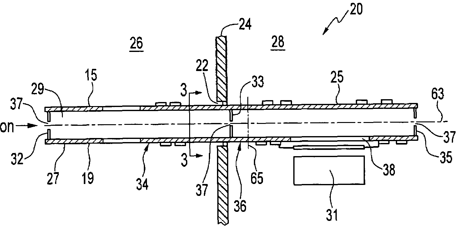
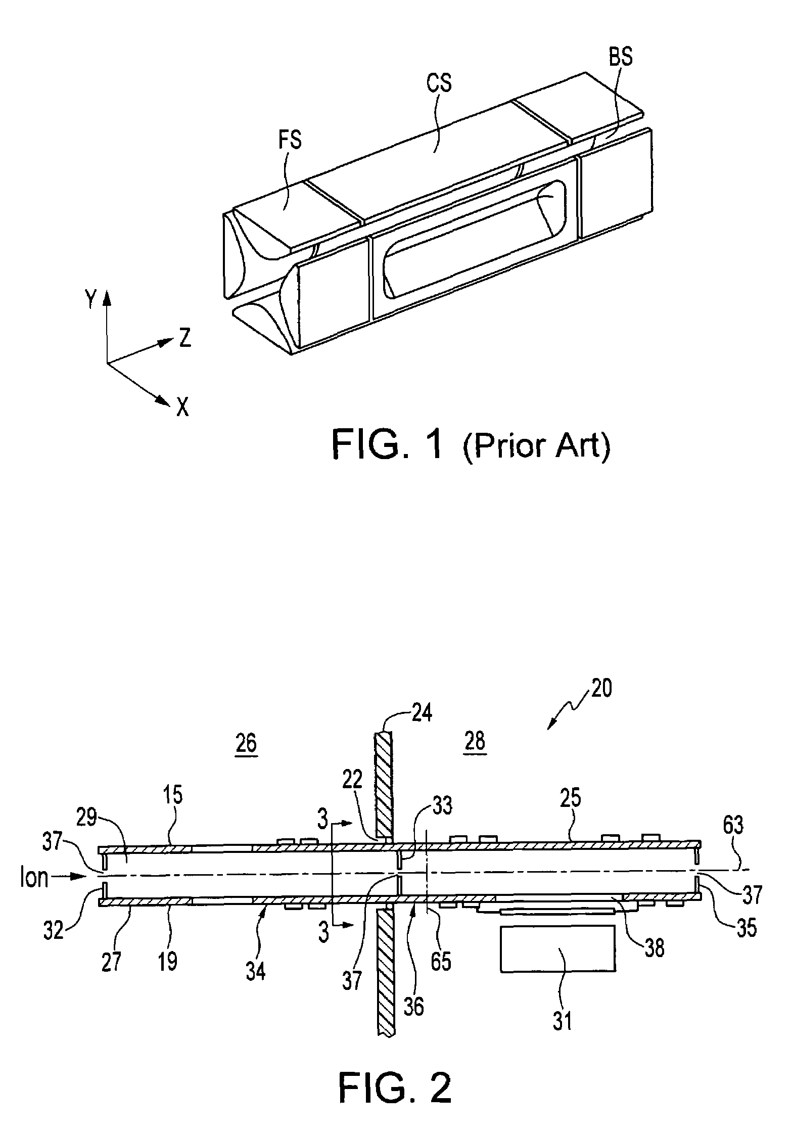
[0029]Referring now to the drawings and first to FIGS. 2 and 3, an ion trap mass analyzer, indicated generally by reference numeral 20, extends through an orifice 22 in a wall 24. The wall 24 separates vacuum chambers 26 and 28, which are maintained at different environmental pressures. The ion trap mass analyzer 20 has an elongated, tube-like structure 27 and a detector 31.

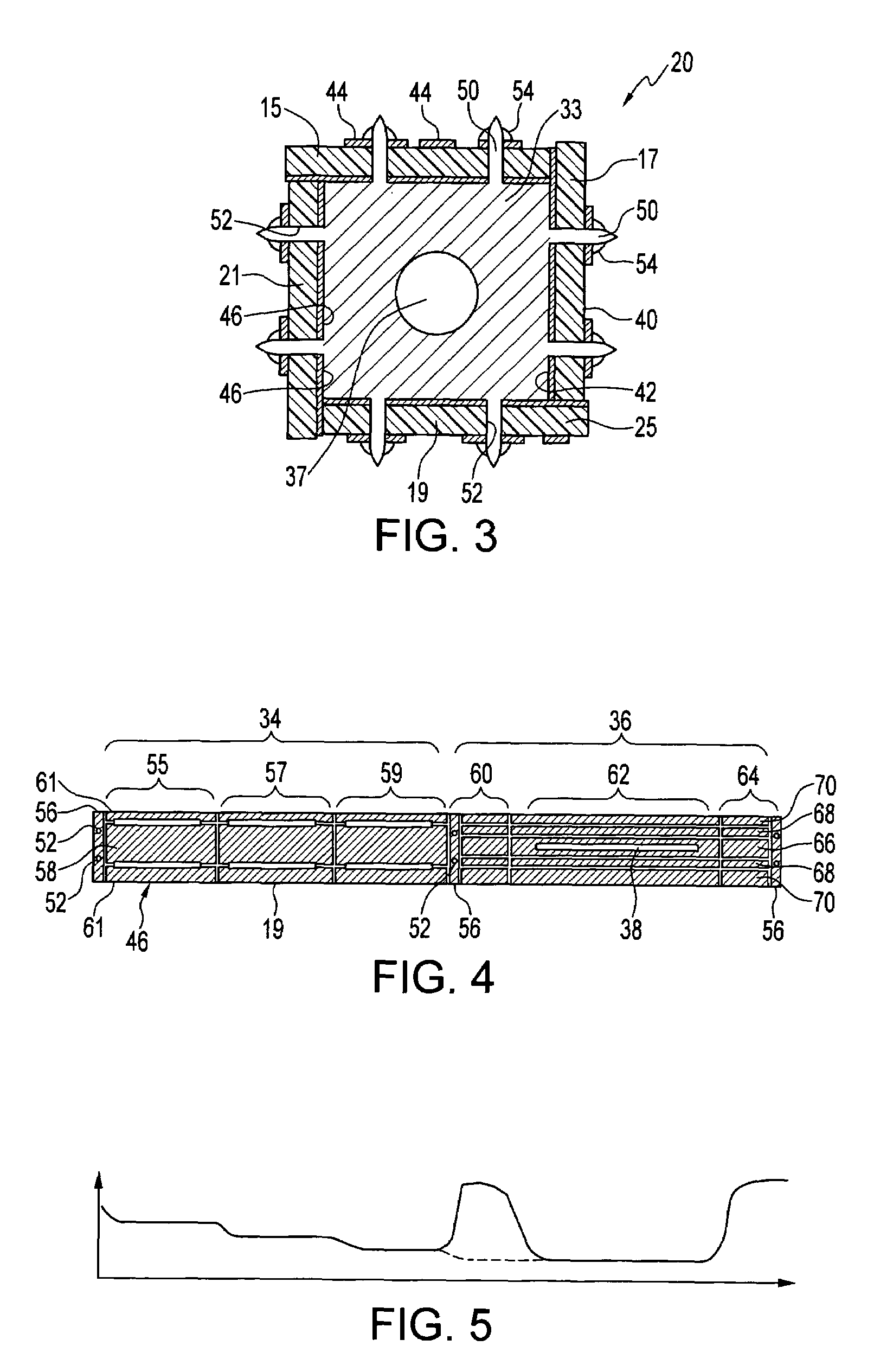
[0030]The elongated structure 27 has a wall 25, and the wall 25 has an insulator substrate. In other embodiments the wall 25 can comprise other types of substrates, e.g. a semiconductor substrate. In this example, the wall 25 includes four elongated printed circuit boards (PCBs) 15, 17, 19 and 21, which are best shown in FIG. 3. The PCBs 15, 17, 19 and 21 are arranged side-by-side along their longitudinal axis, and each of the PCBs 15, 17, 19 and 21 is substantially perpendicular to respective adjacent PCBs 15, 17, 19 and 21. Therefore the elongated structure 27 is in the form a tunnel 29 having a longitudinal ax...


PUM

PropertyMeasurementUnit
pressureaaaaaaaaaa
mass to charge ratioaaaaaaaaaa

Abstract

An ion trap mass analyzer includes an elongated tunnel that has a wall, a longitudinal axis and an inner space. The wall includes a substrate and conductor trace patterns. There is also a variable electric potential means for providing electric potentials which is connected to the conductor trace patterns. The conductor trace patterns and the variable electric potential means provide a variable electric field within the inner space of the tunnel for transferring, storing, and analyzing ions.

Description

BACKGROUND OF THE INVENTION[0001]1. Field of the Invention[0002]This invention relates to an ion trap mass analyzer, and in particular to an ion trap mass analyzer constructed from printed circuit boards.[0003]2. Description of Related Art[0004]Quadrupole electric fields can be generated by various kinds of quadrupole ion optics. Driven by an RF voltage, these quadrupole ion optics are used for different purposes, e.g. an ion guide for ion transmission, a quadrupole mass filter for mass analysis or ion selection, and an ion trap for storage and analysis of ions. Among these devices, a quadrupole mass filter normally needs a high vacuum to achieve its performance while the ion guide and ion trap can work at a lower vacuum. An ion trap mass spectrometer is formed by combining an ion guide and an ion trap and coupling them to an ion source. A tandem mass spectrometer, otherwise known as an MS-MS, is formed by combining two mass spectrometers in tandem with a collision cell between them...

Claims


Application Information

Patent Timeline
Patent Type & Authority Patents(United States)
IPC IPC(8): H01J49/42H01J49/26G01N30/72
CPCH01J49/004H01J49/422Y10T156/10H05K2201/047H05K1/14
Inventor DING, CHUAN-FAN
Owner FUDAN UNIV
Why Eureka
Try Eureka