Optical cellulose acylate film, polarizing plate and liquid crystal display

a technology of optical cellulose and acylate film, which is applied in the direction of polarizing elements, instruments, transportation and packaging, etc., can solve the problems of affecting the optical compensatory function the re retardation value and rth retardation value of the optical compensator, and the optical compensatory ability thereof also varies, so as to achieve little change in viewing angle characteristics, and favorable retardation values

Active Publication Date: 2009-03-17
FUJIFILM CORP
View PDF16 Cites 26 Cited by
  • Summary
  • Abstract
  • Description
  • Claims
  • Application Information

AI Technical Summary

Benefits of technology

[0069]Using the cellulose acylate film according to the invention, it is possible to provide an optical film which exhibits favorable retardation values both in a film plane of the cellulose acylate film (or in plane) and in a direction perpendicular to the film plane (or along the film thickness direction), and shows from little change in retardation values depending on environmental factors such as humidity.
[0070]The polarizing plate according to the invention makes it possible to give a liquid crystal display which shows little changes in viewing angle characteristics even upon environmental (humidity) changes. The liquid crystal display according to the invention shows little changes in viewing angle characteristics even upon environmental (humidity) changes.

Problems solved by technology

In recent years, however, liquid crystal displays are frequently used under various environmental conditions, e.g., at a high humidity or a high temperature and cellulose ester films obtained by using these techniques suffer from a problem that the optically compensatory functions thereof are worsened under such conditions.
In the case of a cellulose ester film having a high Re retardation value and a high Rth retardation value obtained by using the above techniques, in particular, there arises a problem that its Re retardation value and Rth retardation value vary depending on temperature and humidity and, in its turn, the optically compensating ability thereof also varies.

Method used


Image

  • Optical cellulose acylate film, polarizing plate and liquid crystal display
  • Optical cellulose acylate film, polarizing plate and liquid crystal display
  • Optical cellulose acylate film, polarizing plate and liquid crystal display

Examples


example 1

1. Formation of Cellulose Acylate Film

(1) Cellulose Acylate

[0398]Cellulose acylates differing in acyl group type and the degree of substitution by an acyl group from each other as listed in Table 1 were prepared. After adding sulfuric acid (7.8 parts by weight per 100 parts by weight of cellulose) serving as a catalyst, each carboxylic acid providing the corresponding acyl substituent was added and the acylation was carried out at 40° C. Next, the total degree of substitution and the degree of substitution at the 6-position were regulated by controlling the amount of the sulfuric acid catalyst, the water content and the aging time. Aging was performed at 40° C. Subsequently, low-molecular weight components of cellulose acylate were washed off with acetone.

(2) Preparation of Dope

(2)-1 Cellulose Acylate Solution

[0399]The following cellulose acylate composition was poured into a mixing tank and individual components were dissolved under stirring. After heating to 90° C. for about 10 mi...

example 2

(Construction of Polarizing Plate 01)

[0429]Iodine was adsorbed by a stretched polyvinyl alcohol film to form a polarizer.

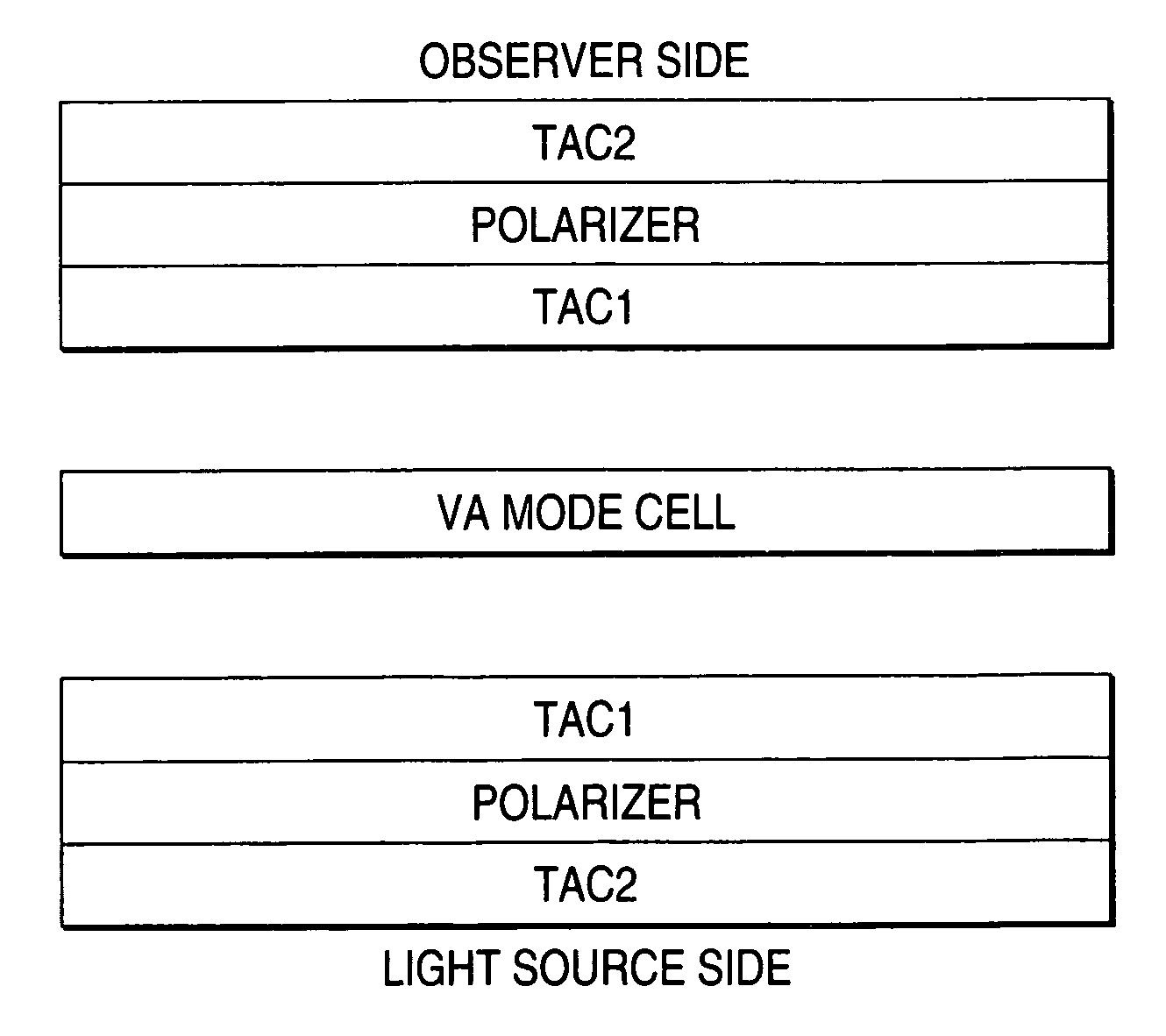
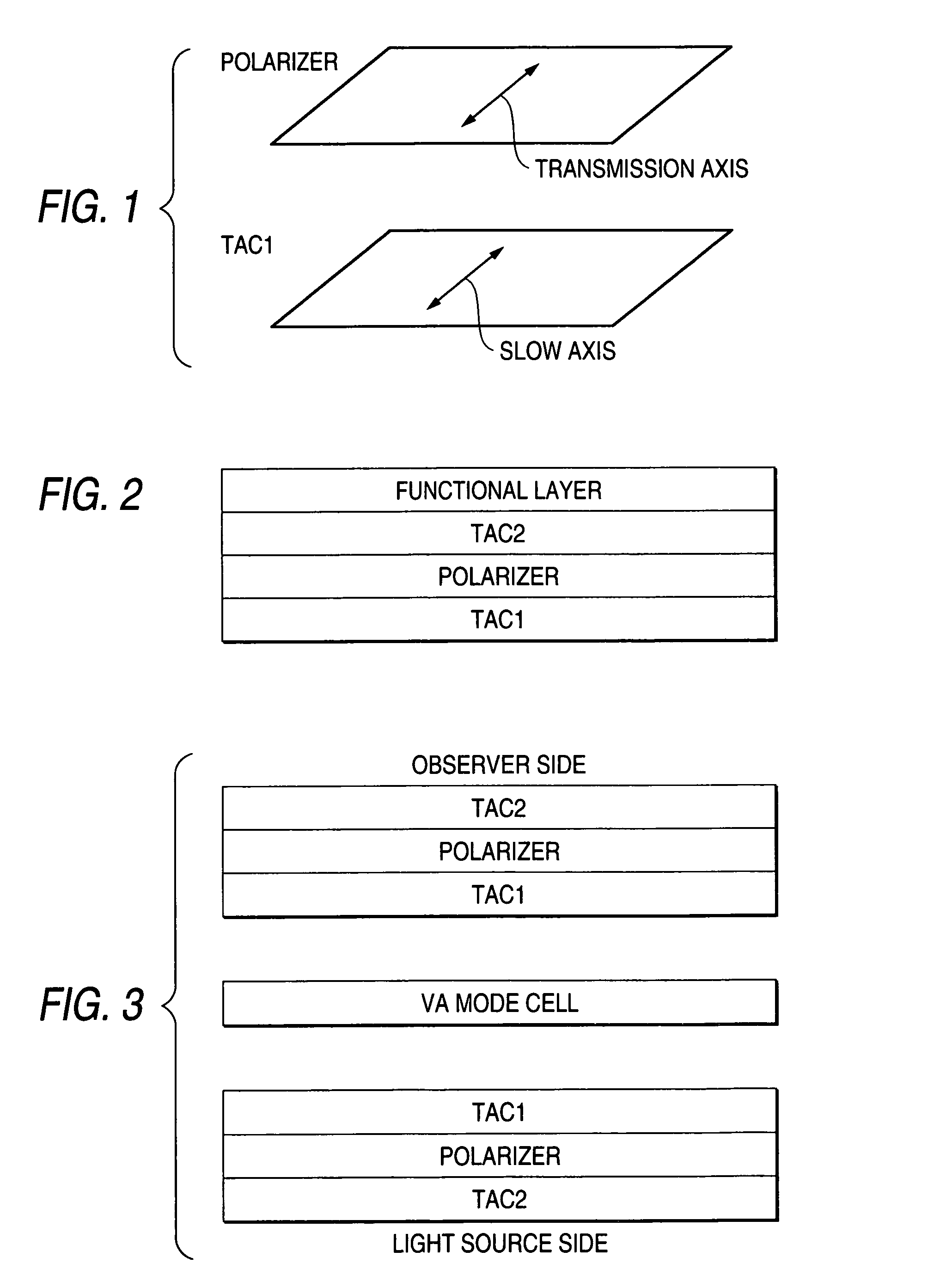
[0430]The cellulose acylate films prepared in EXAMPLE 1 (1-1 to 1-41 and 1-1c to 1-3c: corresponding to TAC1 in FIGS. 1 to 3) were each bonded to one side of the polarizer similar to TAC1 in FIG. 2 with the use of a polyvinyl alcohol-based adhesive. Saponification was carried out under the following conditions.

[0431]A 1.5 mol / L aqueous solution of sodium hydroxide was prepared and maintained at 55° C. A 0.005 mol / L dilute aqueous solution of sulfuric acid was prepared and maintained at 35° C. The cellulose acylate film thus prepared was dipped in the aqueous sodium hydroxide solution for 2 minutes and then dipped in water to thereby sufficiently wash away the aqueous sodium hydroxide solution. Subsequently, it was dipped in the above dilute aqueous sulfuric acid solution for 1 minute and then dipped in water to thereby sufficiently wash away the dilute aqueous sul...

example 3

(Mounting on TN Panel)

[0463]A pair of polarizing plates provided in a liquid crystal display (6E-A3, manufactured by SHARP CORPORATION) using a TN mode liquid crystal cell were stripped off. As substitutes therefor, the polarizing plates A1-16 and A1-2c constructed in EXAMPLE 2 were bonded in such a manner that the films prepared in EXAMPLE 2 were located in the liquid crystal cell side (the slow axes of A1-16 and A1-2c agreeing with the absorption axis of the polarizer). After allowing to stand under environmental temperature-humidity conditions (25° C. and 10% RH, 25° C. and 80% RH) each for 1 month, A1-2c showed remarkable lowering in panel contrast in each of the cases, compared with A1-16. A1-16 was superior in viewing angle characteristics to A1-2c. These results indicate that, with the passage of time, both of the polarizing plates suffered from changes in the optical characteristics and A1-16, which suffered from smaller changes than A1-2c, showed less lowering in panel cont...


PUM

PropertyMeasurementUnit
thicknessaaaaaaaaaa
glass transition temperature Tgaaaaaaaaaa
elastic modulusaaaaaaaaaa

Abstract

To provide an optical film which exhibits excellent retardation values both in the film plane and along the direction perpendicular to the film plane and shows little change in retardation values depending on environmental factors such as humidity, a liquid crystal display showing little change in viewing angle characteristics due to an environmental (humidity) change, and a polarizing plate to be used in the liquid crystal display, the cellulose acylate contains a cellulose acylate which is a mixed fatty acid ester of a cellulose and satisfies formulae specified in the specification, and a polarizing plate and a liquid crystal display using this cellulose acylate film.

Description

BACKGROUND OF THE INVENTION[0001]1. Field of the Invention[0002]This invention relates to an optical cellulose acylate film, and a polarizing plate and a liquid crystal display with the use of the same as an optical compensation sheet.[0003]2. Background Art[0004]Because of having various merits, for example, being available at low voltage, using less power and being available in downsized and thinned form, liquid crystal displays have been widely employed in monitors of personal computers, cell phones and TV sets. According to alignment of liquid crystal molecules in a cell, various display modes are proposed. Among these methods, TN mode, wherein liquid crystal molecules are aligned in a twisted state by about 90° from the lower substrate toward the upper substrate, has been mainly employed so far.[0005]In general, a liquid crystal display generally has a liquid crystal cell, an optical compensation sheet and a polarizer. The optical compensation sheet is employed to prevent a dis...

Claims


Application Information

Patent Timeline
Patent Type & Authority Patents(United States)
IPC IPC(8): C08B3/18G02F1/13363C08J5/18C08L1/14C09K19/52G02B5/30G02F1/139
CPCC08J5/18C08L1/14G02B5/3083G02F1/13363G02F1/1393C08J2301/14Y10T428/1077G02F2001/133635G02F2202/40Y10T428/1036Y10T428/1041Y10T428/105C09K2323/03C09K2323/031C09K2323/035C09K2323/057G02F1/133635
Inventor KAWANISHI, HIROYUKIOHTANI, SUMIONISHIURA, YOSUKEITO, TADASHI
Owner FUJIFILM CORP
Why Eureka
Try Eureka