Dye, dye production method and ink containing dye

a dye and ink technology, applied in the field of dyes, can solve the problems of poor image reproducibility, poor color reproducibility of image and image transparency, and inks containing water-soluble dyes, and achieve excellent color tone, excellent light resistance, ozone resistance and humidity resistance.

Inactive Publication Date: 2009-03-17
CANON KK
View PDF26 Cites 20 Cited by
  • Summary
  • Abstract
  • Description
  • Claims
  • Application Information

AI Technical Summary

Benefits of technology

[0011]It is an object of the present invention to provide a dye that has excellent spectral reflectivity characteristics such as color developability, transparency and the like and that exhibits excellent light resistance, ozone resistance and humidity resistance especially when used in image formation. It is also an object of the present invention to provide an industrially advantageous method of producing this dye. It is another object of the present invention to provide an aqueous ink which can provide an image having good color tone, yet which also has excellent storage stability, when used as an ink used for inkjet recording. It is still another object of the present invention to provide a green ink having good characteristics through the use of this dye together with a copper phthalocyanine compound.
[0021]The present invention provides a dye, and an industrially advantageous method of producing the dye, which has excellent spectral reflectivity characteristics such as color developability, transparency and the like, and when used in image formation, is effective in providing an image that exhibits high weatherfastness and humidity resistance. By using this dye for the coloring material used in an ink, an aqueous ink can be provided which has good color tone. Such an aqueous ink can be, for example, effectively used as an ink used in inject recording. Further, by using a copper phthalocyanine compound as an additional dye in the excellent dye provided by the present invention, a more effective green ink, and especially a green ink used in inject recording, can be provided.

Problems solved by technology

While water-soluble dyes are usually used as coloring materials constituting the inks used for inkjet recording in this case, a recorded image formed from an ink which contains a water-soluble dye normally suffers from the problem of having poor image durability.
On the other hand, although inks which use a pigment for the coloring material form recorded images that have excellent durability, light tends to scatter as a result of the pigment particles.
Thus, compared with inks using a dye, inks using a pigment have suffered from the separate problem that color reproducibility of the image and transparency of the image have been poor.
However, when an image is formed using the dye described in this publication as the ink component, the obtained image has the problem that it does not have sufficient weatherfastness, especially ozone resistance.
Further, the humidity resistance of the image is also insufficient.
However, these conventional production methods suffer from problems with availability of their raw materials, restrictions on their application scope, and that in many cases their yield is low.
However, no examples in which the Ritter reaction was applied to a pyridone compound have, until now, been reported.

Method used


Image

  • Dye, dye production method and ink containing dye
  • Dye, dye production method and ink containing dye
  • Dye, dye production method and ink containing dye

Examples


example 1

[0087]A dye represented by general formula (1) was obtained in the following manner.

synthesis example 1

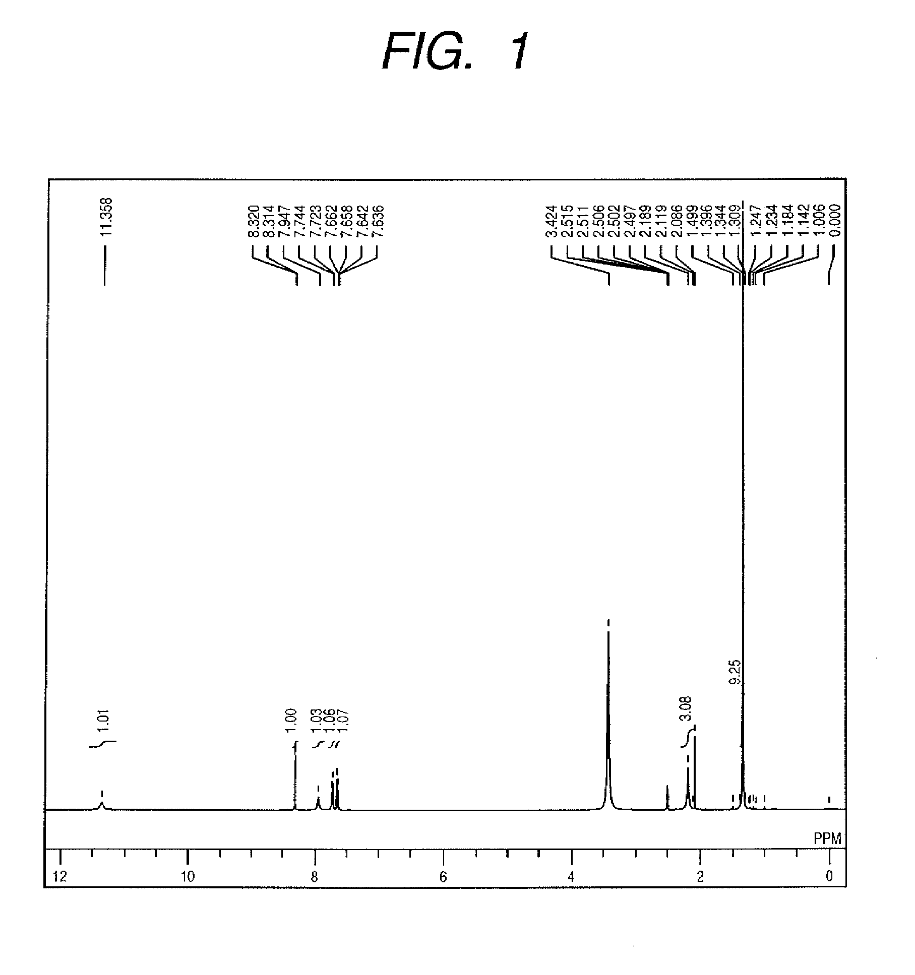
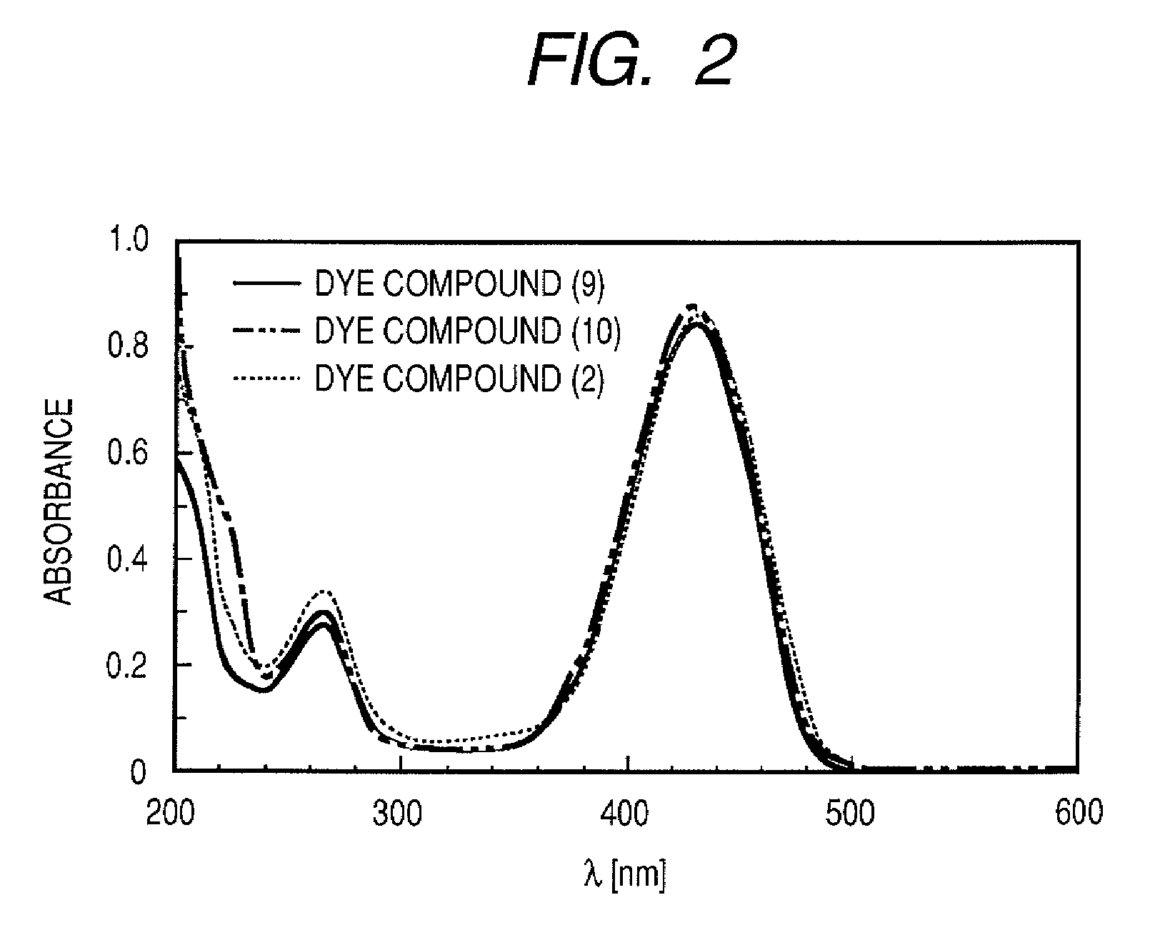
[0088]A compound (9) represented by the following formula was synthesized as the dye represented by general formula (1), wherein the X1 and X3 of formula (1) were hydrogen atoms, X2 was —SO3M, R1 was a hydrogen atom, R2 was —C(CH3)3, R3 was —CH3, and M was sodium.

[0089]

[0090]First, a coupler to be reacted with a diazo component was obtained in the following manner. 10.0 g of 2,6-dihydroxy-4-methyl-3-pyridinecarbonitrile (the compound of general formula (3)) was used as the nitrile compound, and 12.4 g of tert-butanol was used as the alcohol to be reacted with this. 50 mL of glacial acetic acid was used as the reaction solvent, and 20 mL of concentrated sulfuric acid was used as the acid catalyst. These materials were, while cooling with ice and stirring, reacted at 0° C. for 3 hours. The temperature of the reacted solution was slowly returned to room temperature and reaction was continued while stirring for 24 hours. Then, the resultant reaction solution was poured into 1,800 mL of ...

synthesis example 2

[0102]A compound (10) represented by the following formula was synthesized as the dye represented by general formula (1), wherein the X1 and X3 of formula (1) were hydrogen atoms, X2 was —SO3M, R1 was a hydrogen atom, R3 was —CH3, R2 was —C(CH3) C6H4SO3M, and M was sodium.

[0103]

[0104]First, a coupler to be reacted with a diazo component was obtained in the following manner. 10.0 g of 2,6-dihydroxy-4-methyl-3-pyridinecarbonitrile (the compound of general formula (3)) was used as the nitrite compound, and 41.2 g of 80% sodium p-styrenesulfonate was used as the alkene to be reacted with this. 50 mL of glacial acetic acid was used as the reaction solvent, and 30 mL of concentrated sulfuric acid was used as the acid catalyst. The nitrite compound and the alkene were charged into the reaction solvent and acid catalyst under stirring and while maintaining the temperature at 10° C. or less over 1 hour. The temperature of the resultant solution was subsequently increased to between 45 and 50...


PUM

PropertyMeasurementUnit
temperatureaaaaaaaaaa

Abstract

The present invention is a dye represented by the following general formula (1), a method of producing the dye and an ink containing the dye,wherein R1 represents a hydrogen atom, an alkyl group that may be substituted, an aryl group that may be substituted or an aralkyl group that may be substituted; R2 represents an alkyl group that may be substituted, a cycloalkyl group that may be substituted or an aralkyl group that may be substituted; R3 represents an alkyl group that may be substituted, an aryl group that may be substituted or an aralkyl group that may be substituted; X1 through X3 independently represent a hydrogen atom or any substituent; and M represents a counter ion.

Description

BACKGROUND OF THE INVENTION[0001]1. Field of the Invention[0002]The present invention relates to a dye having a novel structure, a method of producing the dye and an ink containing the dye.[0003]2. Description of the Related Art[0004]As a result of the dramatic development in recording technology in recent years, high quality color recording and image output can now be performed very simply. Specifically, it is becoming more common to use personal computers and input / output apparatuses, such as digital cameras, scanners, inkjet printers, color laser printers and the like. Recording apparatuses that employ an inkjet recording method have quickly become popular, since their raw material cost is low, rapid recording can be achieved, it is less noisy during recording, and color recording can be easily provided. This has resulted in calls for even further development of such apparatuses. Specifically, there is a need for a recording apparatus which can more easily output images and docum...

Claims


Application Information

Patent Timeline
Patent Type & Authority Patents(United States)
IPC IPC(8): C09B29/03C09D11/00C09D11/02C09B29/42B41J2/01B41J2/165B41J2/17B41J2/175B41M5/00C09B47/24C09B67/22C09D11/326C09D11/328C09D11/38
CPCC09B29/0007C09B29/363C09D11/328
Inventor TOYODA, TAKAYUKIMURAI, YASUAKIHASEGAWA, WAKAHIROSE, MASASHIFUJIMOTO, KUNIAKIMIYAZAKI, TAKESHI
Owner CANON KK
Why Eureka
Try Eureka