Low-noise ultrasound method and beamformer system for doppler processing

a beamformer and low-noise technology, applied in tomography, instruments, using reradiation, etc., can solve the problems of frequency aliasing, fundamental rate limitations, and the limited ability of pw doppler to measure very high blood flow velocity, so as to achieve wide dynamic range, lower cost, and high power efficiency

Active Publication Date: 2009-04-07
MICROCHIP TECH INC
View PDF9 Cites 19 Cited by
  • Summary
  • Abstract
  • Description
  • Claims
  • Application Information

AI Technical Summary

Benefits of technology

[0034]By way of introduction, the present invention includes a Doppler beamformation method and a beamformer system. The Doppler beamforming method allows one to achieve a wide dynamic range while operating in a low-voltage environment. The new Doppler beamformer outperforms the prior art by simplicity, versatility, lower cost, and higher power efficiency, while maintaining programmability for phase rotating.

Problems solved by technology

This allows one to obtain only samples of the Doppler signal with the pulse repetition frequency, the PRF, which introduces the problem of frequency aliasing.
Besides, due to limitations in the PRF rate, PW Doppler has limited ability to measure very high blood flow velocities.
The rate limitations are fundamental because the transmitted pulse must reach the target and echoes are reflected back to the receiver before the next pulse can be sent.
In comparison with PW Doppler, it is more difficult for CW techniques to distinguish between the transmitted signal and the reflected signal originated by moving blood.
First, since the transmitted signal is continuous and relatively high in amplitude, it generates interference in the receiver.
Second, the high-amplitude echoes reflected from stationary tissue, typically called “clutter,” do not contain a frequency shift but occur simultaneously with the signals that represent blood flow.
Further, conventional CW Doppler processors have a limited dynamic range due to the limited dynamic range of the analog-to-digital converters (ADCs).
Thus, the clutter filtering that precedes the ADC must be much more complex, so that the signal that feeds the converter contains as little clutter content as possible.
Such architecture requires using expensive switches and precision components.
For the phased array, i.e., multi-channel ultrasound systems, it causes a substantial increase in the component count and cost that makes this approach impractical.
However, referring to a single-channel receiver, Fazioly does not disclose any aspect of CW Doppler data acquisition with a phased-array transducer.
First, the per-cannel quadrature mixers, 102 and 104, comprise two transistor pairs switching at the LO frequency. While switching, the gates (bases) of the pair exhibits charge fluctuations. Having a spectral density proportional to 1 / f, these fluctuations are transferred to the output by multiplication with a time-varying transconductance of the switching pair. Since transconductance of the pair is varied at the 2×LO frequency, it contains only even-order harmonics of the LO. This means that flicker noise from the switching pair will directly appear at the output around DC, i.e., in baseband. (Sometimes this noise is referred as the phase noise.) For an N-channel beamformer, the resulting 1 / f noise from switching is increased for a factor of N1 / 2 as compared with a single channel. However, since the beamformer signal gain is equal to N, the signal-to-noise ratio (SNR) is improved by a factor of N1 / 2.
Another source of flicker noise is subsequent summing inherently associated with the process of beamforming.
It can be seen that flicker noise associated with subsequent summing stages increases the system noise floor by a factor of 7-8 dB that substantially degrades the performance of beamforming provided in the baseband.
However, in a low-voltage system this approach is practically inapplicable since clutter would desensitize the beamformer before the signals from blood flow become sufficiently large.

Method used


Image

  • Low-noise ultrasound method and beamformer system for doppler processing
  • Low-noise ultrasound method and beamformer system for doppler processing
  • Low-noise ultrasound method and beamformer system for doppler processing

Examples


second embodiment

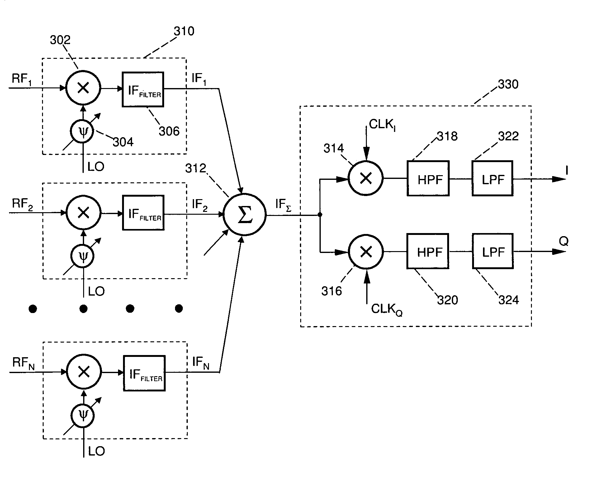
[0066]The foregoing description of the beamforming process assumed identity of the Doppler channels. While this is essentially true for multi-channel ICs in terms of gain and delay matching, the deviation of the filter response because of component tolerances might be an important factor to consider. FIG. 5 depicts CW Doppler beamformer allowing one to minimize the circuit sensitivity to variation in component values.

[0067]As illustrated, CW Doppler beamformer in FIG. 5 also comprises a plurality of N identical Doppler channels 510, an N-input summer 512, a downstream processor 530, and a multi-phase clock oscillator 540. Moreover, said summer, downstream processor, and clock oscillator are duplicates of respective units in FIG. 4.

first embodiment

[0068]Contradictory to the first embodiment, Doppler channel 510 has no IF filters but outputs both sidebands of the mixing process. Instead of per-channel filtering, there is a single IF filter 560 arranged to select either sideband of the beamformed signal MIXΣ. This approach avoids the problem of channel identity at the expense of doubling the amplitude range of signals at the channel output.

[0069]Important advantages of the above embodiments of the present invention can be summarized as follows:[0070]1. Implementing a direct-conversion CW Doppler beamformer, the spectrum of the per-channel quadrature components occupies the same frequencies as flicker noise. This overlapping substantially reduces the resulting SNR of D-mode acquisition.[0071]2. Translating a received RF signal to an IF, beamforming may occur at the frequency range, which is above of the 1 / f corner. Consequently, the proposed technique allows to improve the SNR as compared with prior art.[0072]3. Summing multiple...


PUM


Abstract

An ultrasonic low-noise analog beamformer for Doppler acquisition achieves high sensitivity by translating the frequency of the ultrasound echoes to an intermediate frequency, which is well above of the 1 / f corner. This is accomplished by beamforming the downconverted RF signals instead of using their baseband representation. The baseband conversion, succeeding the beamformation, also incorporates the steps of clutter filtering and anti-aliasing. The invention is particularly suitable for low-voltage process technologies that support broadband applications.

Description

RELATED APPLICATION[0001]This patent application is claiming the benefit of U.S. Provisional Patent Application having a Ser. No. 60 / 617,386, filed Oct. 8, 2004 in the name of Lazar A. Shifrin, and entitled “Low-Noise Ultrasound Method and Beamformer System for Doppler Processing”.BACKGROUND OF THE INVENTION[0002]1. Field of the Invention[0003]This invention relates to coherent ultrasound imaging systems and, more particularly, to phased array ultrasound imaging systems operating in different scan formats and imaging modes. Specifically, but not limited to, the invention relates to phased array beamformer system with low-noise Doppler data acquisition.[0004]2. Description of the Related Art[0005]Medical ultrasound imaging systems are capable of many different modes of operation. One of these is the Doppler mode dedicated to displaying the movement of blood within a vein or an artery.[0006]Doppler imaging can be performed using either continuous wave (CW) or pulse wave (PW) technique...

Claims


Application Information

Patent Timeline
Patent Type & Authority Patents(United States)
IPC IPC(8): A61B8/14
CPCA61B8/06G01S15/8979
Inventor SHIFRIN, LAZAR A.
Owner MICROCHIP TECH INC
Why Eureka
Try Eureka