Radiation image pickup apparatus and its control method

a pickup apparatus and image technology, applied in the field of radioation image pickup apparatus, can solve the problems of reducing s/n, increasing the number of operational amplifiers, and high manufacturing costs, so as to reduce the distance between signal wiring and the signal, reduce the number of external noise components through a space or wiring, and reduce the number of noise components

Inactive Publication Date: 2009-04-07
CANON KK
View PDF5 Cites 39 Cited by
  • Summary
  • Abstract
  • Description
  • Claims
  • Application Information

AI Technical Summary

Benefits of technology

[0043]The present invention is made to solve the above problems and its object is to provide a radiation image pickup apparatus capable of improving the S / N ratio while restraining noises, preferably capable of performing stable and high-speed dynamic-image photographing and capable of restraining dark current and its control method.
[0045]According to the present invention, it is possible to decrease the distance between a signal wiring and at least either of a bias power source and a reset power source and decrease the number of external noise components through a space or wiring. Therefore, it is possible to decrease the number of noise components such as random noises or line noises. Moreover, because a first field-effect transistor is the source-follower type, it is possible to restrain attenuation of a signal due to a capacitive element being parasitic on a signal wiring. Therefore, it is possible to improve the S / N ratio. Moreover, because it is possible to avoid a circuit configuration for connecting an operational amplifier to each signal wiring, it is possible to decrease current consumption. Furthermore, it is possible to make a medical environment higher than the present one in quality in a future aging society.
[0046]Furthermore it is possible to use a material and design same as those of a readout circuit unit for a bias power source and / or reset power source set in a readout circuit unit. Therefore, it is possible to decrease noises of a bias power source or reset power source by using, for example, an operational amplifier. Also by this point, it is possible to restrain noise components such as random noises and line noises.
[0047]Furthermore, when using an MIS-type photoelectric converting device and refreshing (or resetting) converting devices from which an electrical signal is read for each line, it is possible to restrain the voltage fluctuation of GND or power-source line, omit the waiting time for each frame and perform stable and high-speed dynamic-image photographing. Furthermore, when using an MIS-type photoelectric converting device, it is possible to restrain dark current compared to a case of using a PIN-type photoelectric converting device and fabricate a radiation image pickup apparatus at a low cost.
[0048]Furthermore, when forming a first field-effect transistor, second field-effect transistor and third field-effect transistor by using amorphous silicon semiconductor as a main material, it is possible to form a converting device and each field-effect transistor on the same substrate. Therefore, it is possible to improve the yield of radiation image pickup apparatuses in fabrication.

Problems solved by technology

Therefore, because a constituting method becomes complex compared to the case in FIG. 11, the manufacturing cost may become high.
Therefore, it is unnecessary to perform the refresh operation described for the MIS-type photoelectric converting device.
In this case, because noise components of a rear-stage readout circuit unit to be connected to a signal wiring, for example, the so-called circuit noises such as thermal noises of a resistance and shot noises of a transistor are not zero, there is a problem in that S / N is lowered.
This problem occurs when the photoelectric converting device is either the MIS-type or the PIN-type.
However, this structure has the problem that the number of operational amplifiers increases and the chip size increases.
Moreover, there are problems in that current consumption increases and calorific output increases.
Furthermore, problems that a cooling mechanism must be mounted and, thereby, the apparatus becomes more complex are induced.
However, because the noises are buried in noises of a rear-stage read circuit, they tend not to become comparatively conspicuous as images.
However, in the case of the apparatus disclosed in U.S. Pat. No. 6,600,160B1, noise components by the bias power source performs scanning in an image pickup circuit unit or sample holding in a reading circuit unit for every line similarly to the case of a signal.
Therefore, there is a problem of inducing horizontal-line noises (hereafter referred to as line noises).
The system disclosed in U.S. Pat. No. 6,600,160B1 is able to read signals of a photoelectric converting device without loss and outputting them to a readout circuit unit by the system includes a problem that it has no resistance against external noises incoming to the photoelectric converting device, particularly the bias wiring.
However, because the PIN-type photodiode requires two junctions such as PI junction and IN junction, it has the problem that dark current increases.
This represents that there is a problem that a laminated structure is formed because it is necessary separately to fabricate a TFT and a photoelectric converting device, and as a result the structure is disadvantageous in yield and cost.
However, by switching the bias power source of the photoelectric converting device, it is necessary to perform the refresh operation and there is a problem that the speed is decreased by the time equivalent to the refresh operation.
Particularly, in the case of a medical image pickup apparatus, the area increases and the number of pixels is inevitably increased.
That is, a system for simultaneously refresh bias wirings has a problem that it is impossible to achieve a high frame rate as a dynamic image.
Thus, in the case of the prior art for refreshing all photoelectric converting devices once for every operation for reading one frame, dynamic-image photographing is difficult.

Method used


Image

  • Radiation image pickup apparatus and its control method
  • Radiation image pickup apparatus and its control method
  • Radiation image pickup apparatus and its control method

Examples


second embodiment

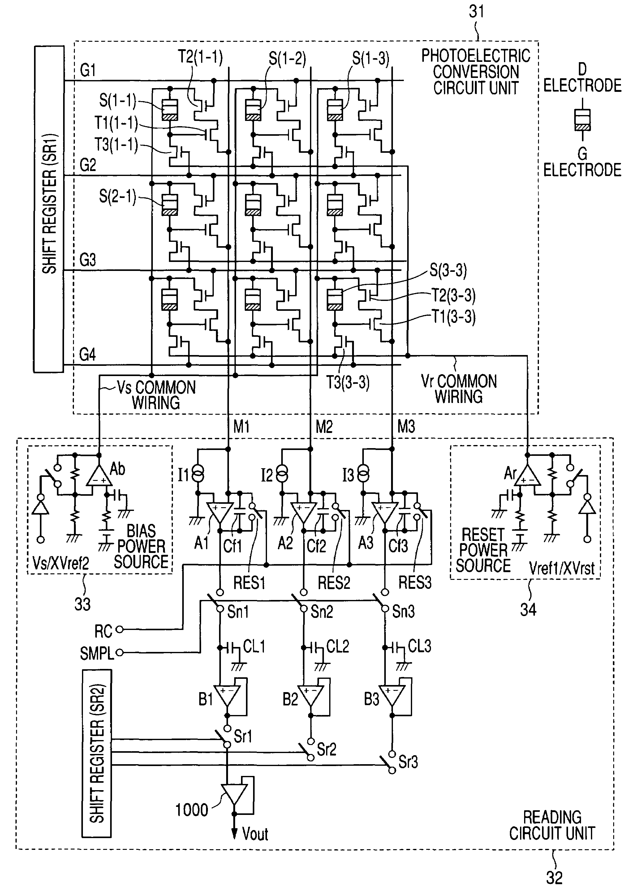
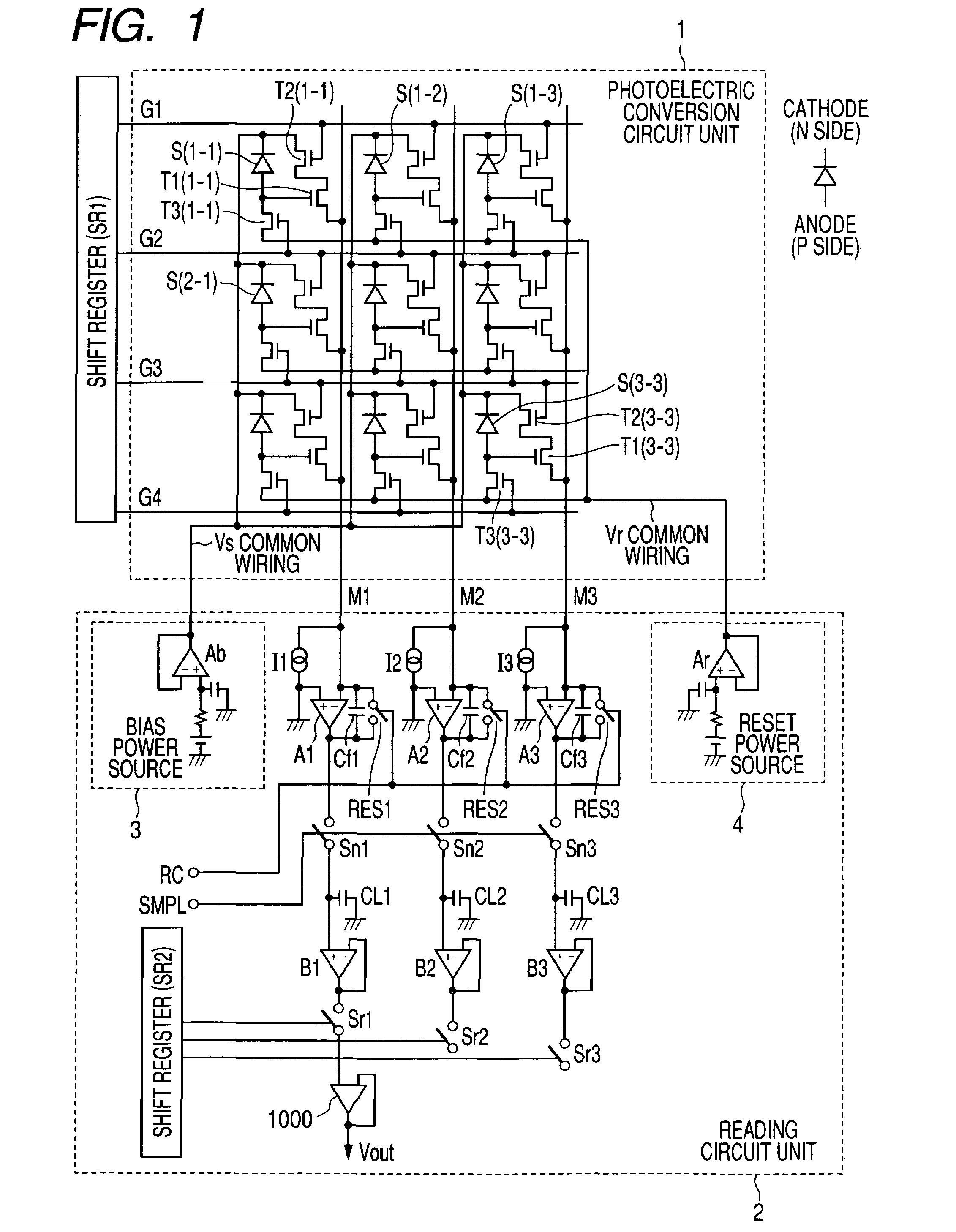
[0092]Then, second embodiment of the present invention is described below. FIG. 3 is an illustration showing a two-dimensional circuit configuration of the X-ray image pickup apparatus (radiation image pickup apparatus) according to the second embodiment of the present invention. FIG. 3, shows 9 pixels=3×3 pixels in order to simplify description.

[0093]In FIG. 3, S(1-1) to S(3-3) are photoelectric converting devices for converting visible light in which X-rays are converted by a wavelength converting member into electrical signals and are MIS-type photoelectric converting devices in the case of this embodiment. T1(1-1) to T1(3-3) are first TFTs in which the G electrode of each photoelectric converting device is connected to a gate terminal. T2(1-1) to T2(3-3) are second TFTs set to selectively read an electrical signal of a photoelectric converting device for each line in scanning. T3(1-1) to T3(3-3) are third TFTs set to refresh or reset a photoelectric converting device from which ...

third embodiment

[0114]Now, the third embodiment of the present invention is described below. In the case of the third embodiment, the X-ray image pickup apparatus of the second embodiment is changed from the radioscope mode (dynamic image mode) to the radiographing mode (static image mode) in accordance with a request of an operator for radiographing a static image. FIG. 5 is an illustration showing a radiographing sequence of the X-ray image pickup apparatus of the third embodiment of the present invention. FIG. 6 is a time chart showing operations of an X-ray image pickup apparatus in the radioscopic mode (dynamic image mode) and FIG. 7 is a time chart showing operations of an X-ray image pickup apparatus in the radiographing mode (static image mode).

[0115]In the radioscopic mode, the timing operation shown in FIG. 6 is repeated. In the period of the radioscopic mode, an operator monitors the radioscopic image of a patient in order to decide the position and angle of an object (patient) for radio...

fourth embodiment

[0121]Now, the fourth embodiment of the present invention is described below. FIG. 9 is a schematic view showing a structure of the X-ray image pickup apparatus (radiation image pickup apparatus) of the fourth embodiment of the present invention.

[0122]In the case of this embodiment, a readout circuit unit and a drive circuit unit are respectively divided into a plurality of blocks and are connected to a photoelectric conversion circuit unit. Black squares (|) in FIG. 9 respectively show one pixel and a circuit for the one pixel is shown in the circle (◯) in FIG. 9. In the case of this embodiment, an MIS-type photoelectric converting device, first TFT, second TFT and third TFT are included in pixels similarly to the case of the second embodiment. However, it is allowed to use a PIN-type photoelectric converting device as a photoelectric converting device similarly to the case of the first embodiment.

[0123]Blocks of the readout circuit unit are shown as AMP-IC1 to AMP-IC10 and blocks ...


PUM


Abstract

Each pixel is provided with a photoelectric converting device or the like, a source-follower-type first transistor or the like, a second transistor to be turned on when reading an electrical signal from a pixel selected by a shift register for each line and outputting the signal to a readout circuit unit and a third transistor to be turned on when resetting a photoelectric converting device set to a pixel selected by a shift register for each line. Moreover, a bias power source for supplying a photoelectric conversion bias to a photoelectric converting device and a reset power source for supplying a reset bias to a photoelectric converting device are set in the readout circuit unit. By using the radiation image pickup apparatus and its control method, it is possible to improve the S / N ratio while restraining noises and preferably, it is possible to perform stable and high-speed dynamic-image photographing and restrain dark current.

Description

[0001]This application claims priority from Japanese Patent Application No. 2004-148051, filed on May 18, 2004, which is hereby incorporated by reference herein.BACKGROUND OF THE INVENTION[0002]1. Field of the Invention[0003]The present invention relates to a radiation image pickup apparatus and its control method, preferably used for medical diagnosis and industrial non-destructive inspection. In the case of the present invention, electromagnetic waves such as X-rays and γ-rays as well as beams of α and β particles are included in the term “radiation”.[0004]2. Description of the Related Art[0005]Conventionally, an X-ray radiographing system set in a hospital includes a film photographing system for irradiating X-rays to a patient and exposing to the the Xrays that have passed through the patient a film and an image processing system for converting X-rays into electrical signals and performing digital image processing. As one apparatus for realizing the image processing system, ther...

Claims


Application Information

Patent Timeline
Patent Type & Authority Patents(United States)
IPC IPC(8): G01T1/24H01L27/00H04N5/335G01T1/20A61B6/00G01T1/202H01L27/14H01L27/146H01L31/09H04N5/30H04N5/32H04N5/357H04N5/369H04N5/374H04N5/376
CPCH04N5/32H04N5/361H04N5/3698H04N5/378H04N25/709H04N25/63H04N25/75
Inventor ENDO, TADAOKAMESHIMA, TOSHIOYAGI, TOMOYUKITAKENAKA, KATSURO
Owner CANON KK
Why Eureka
Try Eureka