
Quadrature modulation compensation

a compensation and quadrature technology, applied in the field of communication systems, can solve the problems of reducing the error rate increasing the cost of the qm or qd, and the complexity of the demodulation, so as to reduce the error rate

Inactive Publication Date: 2009-04-07
MAXLINEAR ASIA SINGAPORE PTE LTD
View PDF10 Cites 36 Cited by
  • Summary
  • Abstract
  • Description
  • Claims
  • Application Information

AI Technical Summary

Benefits of technology

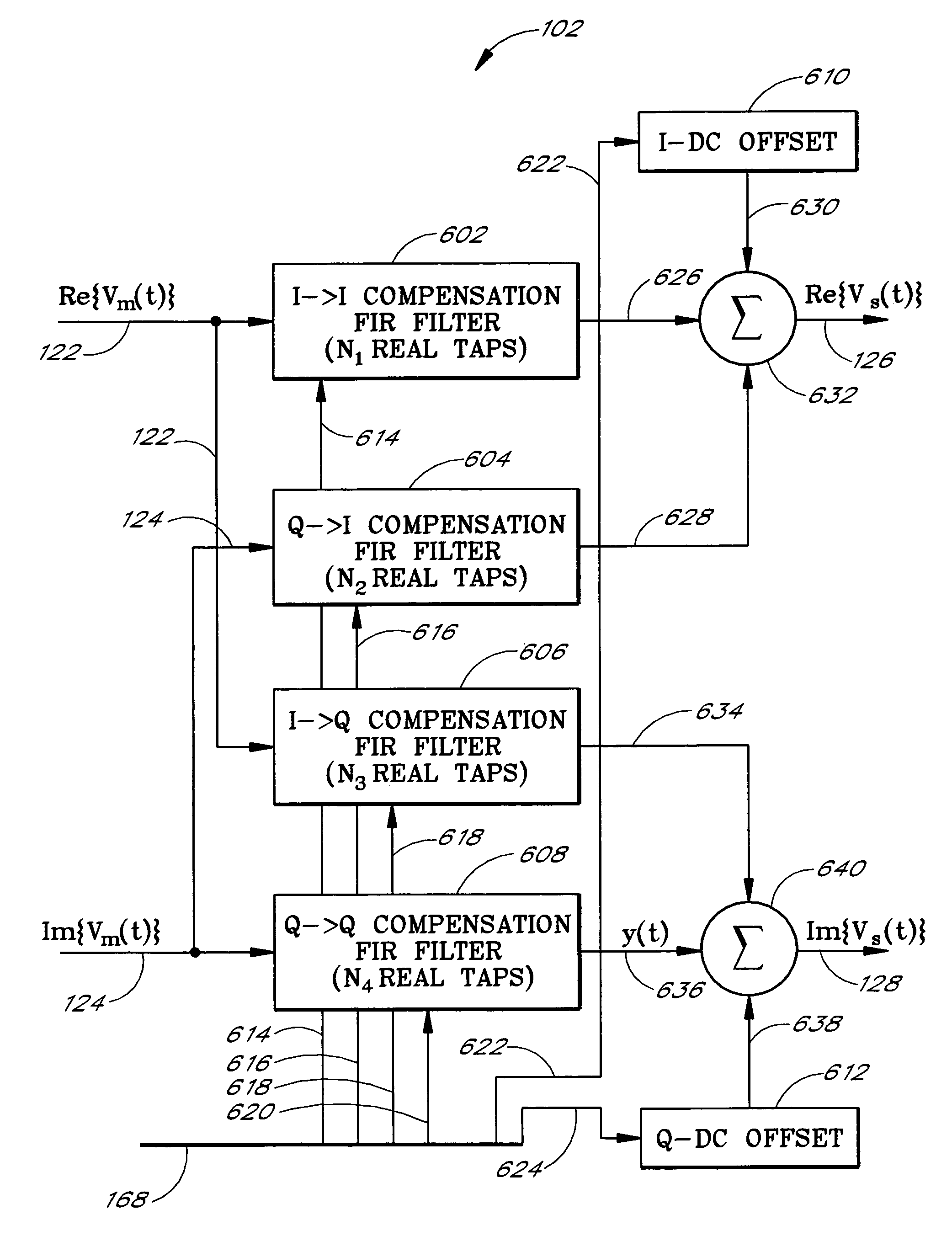
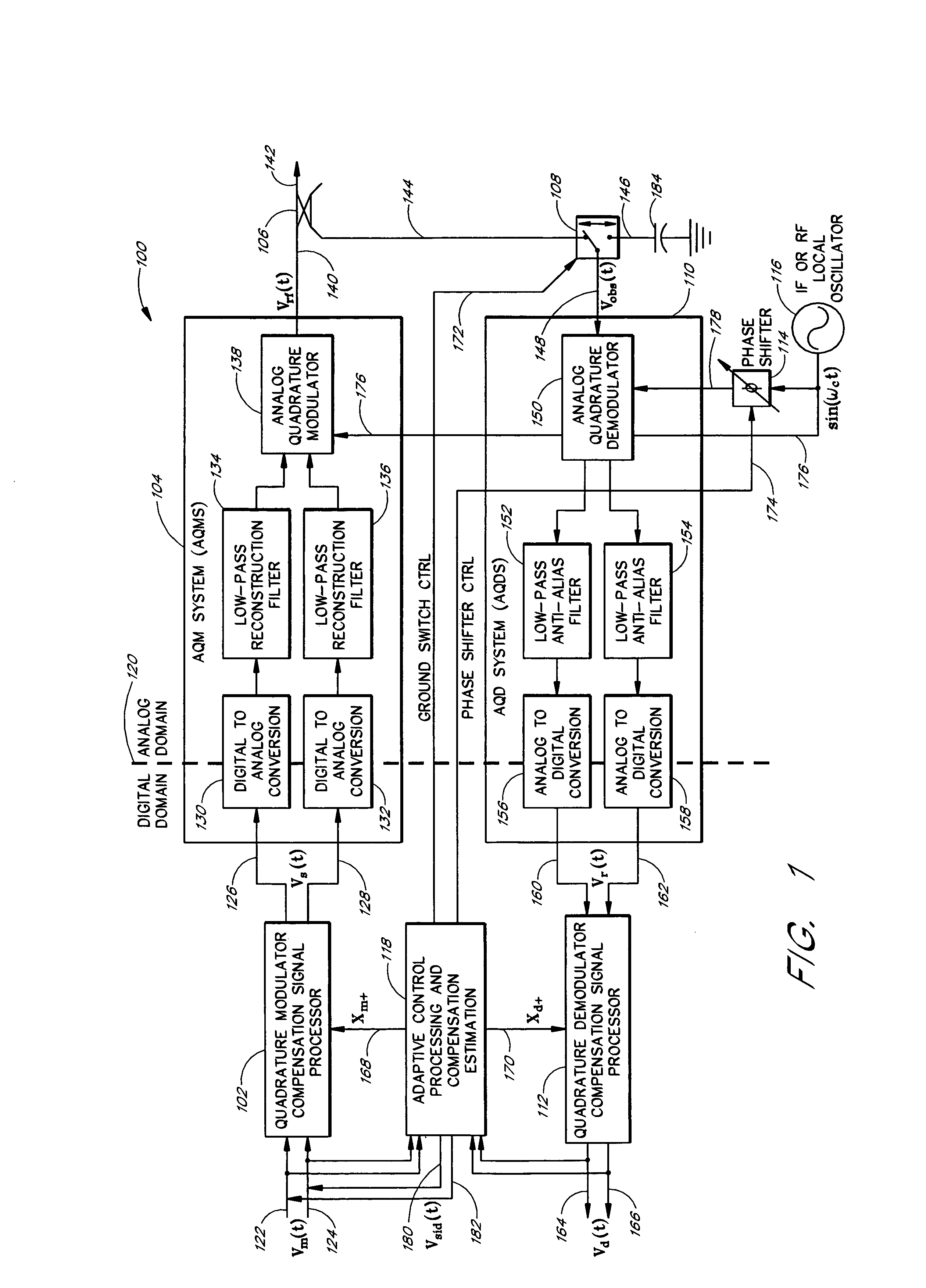
"The present invention provides a compensation system for quadrature modulation and demodulation impairments that is applicable over a wide signal bandwidth. The system includes a quadrature modulator compensation signal processor and a quadrature demodulator compensation signal processor that pre-compensate and post-compensate for the impairments introduced by the analog quadrature modulator and demodulator. The system also includes a phase shifter that shifts the phase of the local oscillator to distinguish quadrature impairments introduced by the modulation and demodulation paths. The compensation processing associated with the forward and reverse paths is sporadically updated to reduce errors between the input signal and the feedback signal. The invention improves the performance and accuracy of quadrature modulation and demodulation without the need for expensive components."

Problems solved by technology

A digital-based QM or QD provides relatively accurate quadrature modulation and demodulation, but is relatively complex and expensive.
Also, where relatively high conversion rates are desired, a digital-based QM or QD frequently requires the addition of a frequency up-converter or a frequency down-converter, respectively, thereby adding expense to the QM or QD.
Further, image-rejection filters that accompany the up-converter add additional cost to a digital-based QM.
Disadvantageously, conventional analog-based QM or QD circuits exhibit less accuracy in the modulation or multiplexing process than digital-based QM or QD circuits.
Further, related components such as digital-to-analog converters and reconstruction filters can also contribute to quadrature impairment.
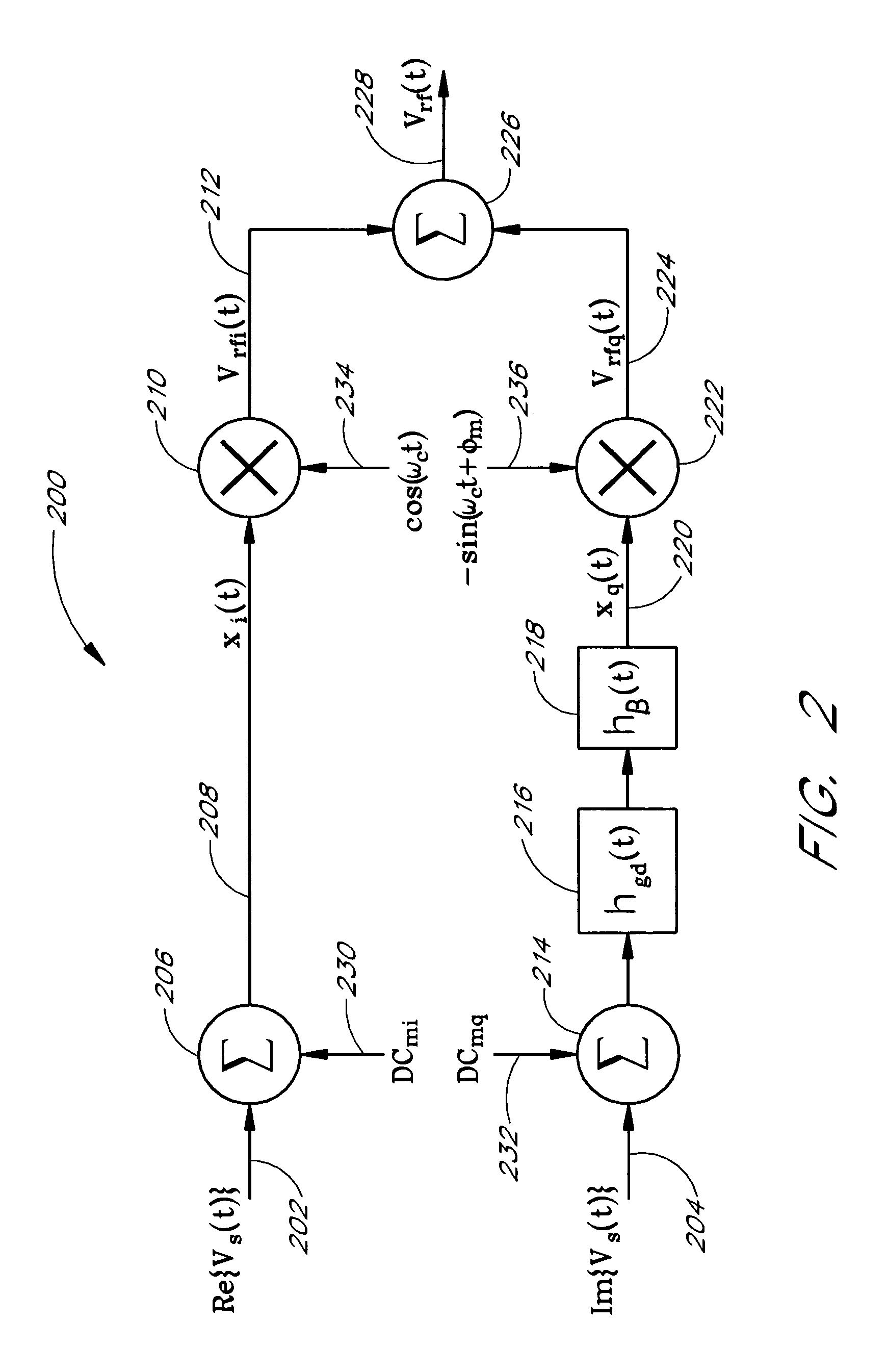
Gain imbalance occurs where the two sinusoids have unequal power, when the two baseband signals (input signals to the quadrature modulator, or output signals from the quadrature demodulator) are amplified / attenuated by different amounts by the quadrature modulation or demodulation device or by supporting hardware, e.g., filters and the like.
Phase imbalance occurs in situations such as where the two sinusoids used in the quadrature modulation / demodulation process exhibit a phase relationship that deviates from 90-degrees, where there are differences in the group delay between the I and Q circuit paths, and the like.
LO feed-through occurs when power at the frequency of the LO used to generate the two sinusoids of the QM process is undesirably present in the output of the quadrature modulator.
The power present at the LO frequency disadvantageously wastes valuable output power.
Similarly, undesired coupling of the LO into a quadrature demodulator results in an undesirable DC offset in the recovered baseband signals.
Conventional compensation techniques for quadrature impairment are inadequate.
However, conventional techniques suffer from several drawbacks, such as relatively low performance and relatively high cost.
Conventional compensation techniques are limited in compensation bandwidth and do not adequately compensate for quadrature impairment across an entire band.
Some conventional techniques employ computationally intensive Fourier transform computations to extend the bandwidth of computation, but are still relatively limited in bandwidth.
Such use of injected test signals is not feasible in all applications because of the interruption to the transmission of the baseband signals that occurs while the test signals are injected.
Circuits and switches to inject test signals also add cost to the compensation system.
Diode detectors add to the cost of a system and are also sensitive to temperature, aging, and other environmental effects, and often require periodic recalibration.
Further, a detector diode typically does not provide an ideal response, such as a predictable linear or logarithmic response, to an RF signal, which thereby limits the amount of compensation attainable with such diode detectors.
In addition, detector diodes can vary over frequency, thereby further limiting the compensation capability of such systems.
Where a modulator includes both QM and QD, conventional compensation techniques fail to distinguish between the quadrature impairment caused by the quadrature modulator and the quadrature impairment caused by the quadrature demodulator.

Method used


Image

  • Quadrature modulation compensation
  • Quadrature modulation compensation
  • Quadrature modulation compensation

Examples


Embodiment Construction

Glossary of Mathematical Symbols

[0045]x*(t): The “*” symbol indicates complex conjugation of the function or data value to which it is applied.[0046]x(t){circle around (x)}y(t): The “{circle around (x)}” symbol indicates convolution of the two signals.[0047]x·y: The “·” symbol indicates multiplication of the two signals or data values.

[0048]Although this invention will be described in terms of certain preferred embodiments, other embodiments that are apparent to those of ordinary skill in the art, including embodiments which do not provide all of the benefits and features set forth herein, are also within the scope of this invention. Accordingly, the scope of the present invention is defined only by reference to the appended claims.

[0049]An embodiment of the present invention advantageously compensates for quadrature impairments of an analog quadrature modulator and / or demodulator over a relatively wide signal bandwidth. Reduction of quadrature impairment is desirable because quadra...


PUM


Abstract

The present invention is related to methods and apparatus that compensate for quadrature impairments of an analog quadrature modulator and / or demodulator over a relatively wide signal bandwidth. One embodiment pre-distorts baseband signals in a quadrature modulator compensation signal processor (QMCSP) to negate the quadrature impairment of an analog quadrature modulator and corrects a received baseband signal in a quadrature demodulator compensation signal processor (QDCSP) to cancel the quadrature impairment of an analog quadrature demodulator. The QMCSP and the QDCSP contain adaptive digital filter correction structures that pre-compensate and post-compensate, respectively, for the quadrature impairments introduced by the analog quadrature modulator and the analog quadrature demodulator over a relatively wide bandwidth. A phase shifter advantageously shifts the phase of a local oscillator signal to the analog quadrature demodulator to distinguish quadrature impairments introduced by the modulation path from quadrature impairments introduced by the demodulation path.

Description

RELATED APPLICATIONS[0001]This application is a divisional application of U.S. application Ser. No. 09 / 771,144, filed Jan. 26, 2001, now U.S. Pat. No. 6,940,916, which claims the benefit under 35 U.S.C. § 119(e) of U.S. Provisional Application No. 60 / 178,385, filed Jan. 27, 2000, the disclosures of which are hereby incorporated by reference herein.BACKGROUND OF THE INVENTION[0002]1. Field of the Invention[0003]The present invention is generally related to communications systems. In particular, the present invention relates to Intermediate Frequency (IF) or Radio Frequency (RF) modulators and demodulators.[0004]2. Description of the Related Art[0005]A component frequently found in a radio frequency (RF) transmitter / receiver (transceiver) is a quadrature modulator (QM) and / or quadrature demodulator (QD). A QM, which is also referred to as a quadrature multiplexer, modulates an intermediate frequency (IF) or an RF signal with the contents of two baseband signals. The baseband signals c...

Claims


Application Information

Patent Timeline
Patent Type & Authority Patents(United States)
IPC IPC(8): H03C3/00H03K7/06H04L27/12H03C3/40H03D3/00H04L5/12H04L23/02H04L27/00
CPCH03C3/40H03D3/008H03D3/009H04L27/0014H04L2027/0016H04L2027/0018H04L2027/0024
Inventor WARNER, WILLIAM DEANSHIN, SOON SUNWRIGHT, ANDREW S.
Owner MAXLINEAR ASIA SINGAPORE PTE LTD
Learn More