
Endovenous closure of varicose veins with mid infrared laser

a laser and varicose vein technology, applied in the field of varicose vein vein laser assisted method and apparatus, can solve the problems of destroying endothelial cells, limiting the efficiency of heat transfer to the vessel wall, and requiring expensive and complicated catheters, so as to prevent damage to surrounding tissue and perforation of the vessel, less energy to be used, and more predictable and controllable

Inactive Publication Date: 2009-04-28
COOLTOUCH
View PDF24 Cites 75 Cited by
  • Summary
  • Abstract
  • Description
  • Claims
  • Application Information

AI Technical Summary

Benefits of technology

[0021]It is an object and an advantage of the present invention to provide an improved method and device that uses a laser wavelength that transmits through any residual blood in the vessels and is absorbed by the water and collagen of the vessel wall. This new technique is more predictable and controllable in the presence of residual blood and is more effective in targeting only the vessel wall.
[0022]Clinical experiments have demonstrated that perforation of the vessel wall does not occur using 1.2 to 1.8 um energy, even if the fiber remains at one location for several seconds. This is because the laser energy is uniformly and predictably absorbed without any hot spots, boiling, or explosions caused by blood pockets.
[0023]Clinical experiments have demonstrated a much lower incidence of pain and collateral bruising using 1.2 to 1.8 um laser energy because the vessel wall always stops the energy. Very little transmits outside the vessel to cause damage.
[0024]Clinical experiments have demonstrated the coagulation of side vessels concurrently with larger vessel treatment due to a wave guiding effect of the 1.2 to 1.8 um laser energy into the smaller vessels. This has not been observed using 500 to 1100 nm laser energy because residual blood will absorb and stop any energy from getting into the branch vessels.
[0025]The present improved device and method in contrast to the teachings of the prior art does not require direct intraluminal contact with the vessel wall because it is less affected by residual blood. The energy passes through the residual blood without boiling or exploding and is absorbed primarily by the vessel wall. This is a significant clinical improvement over the methods of the prior art, with much better control and predictability.
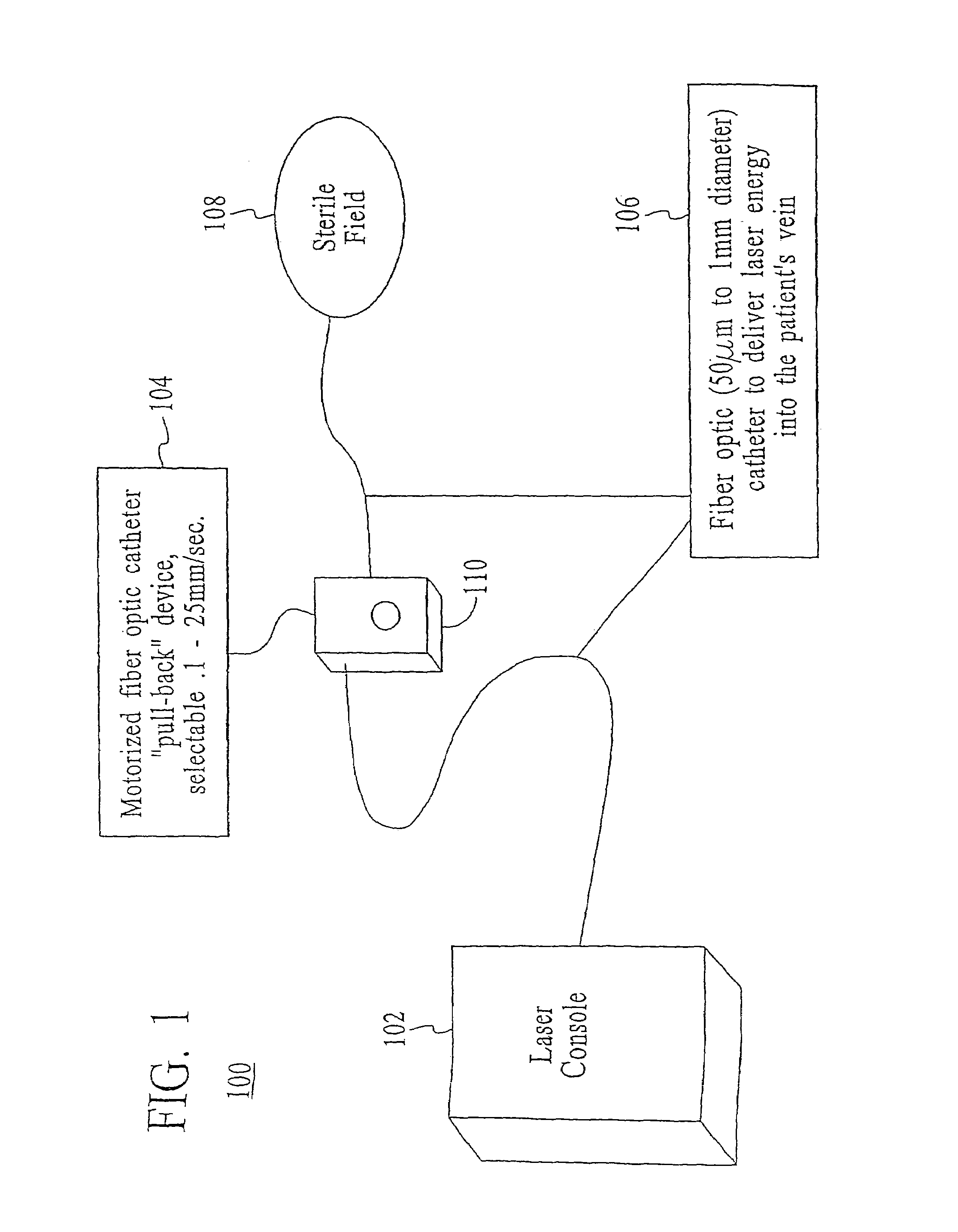
[0026]The present improved device and method may utilize a continuously running laser and energy delivery with a continuous controlled withdrawal rate using a motorized pull back device.

Problems solved by technology

RF technology has been used to try to heat the vessel wall directly but this technique requires expensive and complicated catheters to deliver electrical energy in direct contact with the vessel wall.
Other lasers at 810 nm and 1.06 um have been used in attempts to penetrate the skin and heat the vessel but they also have the disadvantage of substantial hemoglobin absorption which limits the efficiency of heat transfer to the vessel wall, or in the cases where the vessel is drained of blood prior to treatment of excessive transmission through the wall and damage to surrounding tissue.
All of these prior techniques result in poor efficiency in heating the collagen in the wall and destroying the endothelial cells.
This is a major cause of overheating and perforation of the vessel wall as even the best surgeon may have difficulty retracting the fiber at exactly the correct speed to maintain a vessel wall heating temperature of 85 deg C. Other prior art using thermocouples at the tip of the catheter depend on electrical contact between electrodes inside the vessel and are expensive and require very slow catheter-withdrawal (2 cm / min.) and are difficult to use.
This is because the prior art laser wavelengths are not as efficiently coupled to the vessel wall and are instead absorbed in the blood or transmitted through the wall into surrounding tissue.
It will be understood that methods taught in the prior art can be inefficient to such a degree that external cooling is mandatory on the skin surface to prevent burns.
Use of common, standard, non-diffusing tip fiber optic and other laser delivery devices increases the risk for perforation of the cannulated vessel.
See FIG. X. Most of the energy used by this method passes through the vessel wall and causes damage to surrounding tissue.
Operative complications of this technique include bruising and extensive pain caused by transmitted energy and damage to surrounding tissue.
However, this technique does appear to be clinically effective (but misleadingly so) because the blood that remains in the vein after compression absorbs the 500 to 1100 nm energy.
This prior art technique is poorly controlled because the amount of residual blood in the vein can vary dramatically.
The blood can boil and explode in the vessel causing occasional perforation of the vein wall and unnecessary damage to healthy tissue.
This is very difficult to achieve and control.
This is required using their technique because they have no means to uniformly control the rate of energy delivered.
In clinical practice this is very difficult to do and results in excessive perforations and complications.
However, thermal damage with resorption of the GSV has also been seen in veins emptied of blood.
One in vitro study model has predicted that thermal gas production by laser heating of blood in a 6 mm tube results in 6 mm of thermal damage.
Since the anesthetic and access techniques for the two procedures are identical, it is believed that non-specific perivascular thermal damage is the probable cause for this increased tenderness.
Slow uncontrolled pull-back of the catheter is likely one cause for overheating and perforation of the vessel wall as even the best surgeon may have difficulty retracting the fiber at exactly the correct speed to maintain a vessel wall heating temperature of 85 deg C. This technique prevents damage to surrounding tissue and perforation of the vessel.

Method used


Image

  • Endovenous closure of varicose veins with mid infrared laser
  • Endovenous closure of varicose veins with mid infrared laser
  • Endovenous closure of varicose veins with mid infrared laser

Examples


first embodiment

[0100]Turning to FIG. 17, a protective spacer 331 is in the form of a molded body formed near the tip 308 of the fiber optic catheter 306. The fiber optic catheter 306 includes a fiber optic core 310 and a protective outer jacket 311. The fiber optic core 311 typically has a diameter of from about 150 to about 600 um, and the catheter jacket 311 typically has a diameter of from about 300 to about 800 um. The spacer 331 typically has a diameter of from about 400 um to about 1200 um. The spacer 331 is preferably formed from an epoxy, a UV setting cement, or other material suitable for molding onto the external surface of the fiber optic catheter 306. The material used to construct the molded spacer 331 is preferably opaque. The example shown in FIG. 15 is a bulb-shaped molded epoxy spacer 331. As shown in FIG. 15, the spacer 331 is formed on the outer surface of the jacket 311 of the catheter near the tip 308 of the optic fiber 310, but it does not cover the tip 308 or otherwise inter...

second embodiment

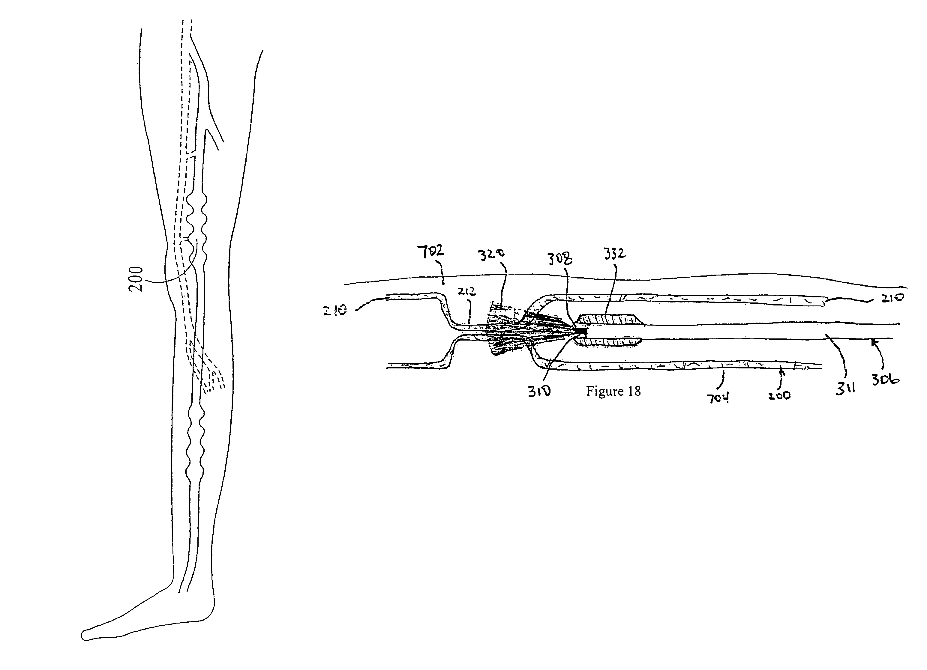
[0101]Turning to FIG. 18, a protective spacer 332 is in the form of a plastic ring or sleeve attached at or near the tip 308 of the fiber optic catheter 306. The fiber optic catheter 306 includes a fiber optic core 310 and a protective outer jacket 311. The fiber optic core 310 typically has a diameter of from about 150 to about 600 um, and the catheter jacket 311 typically has a diameter of from about 300 to about 800 um. The spacer 332 typically has a diameter of from about 400 um to about 1200 um. The spacer 332 is preferably formed of a plastic, such as teflon, nylon, delrin, polyimide, or other suitable plastic material, and is preferably opaque. Alternatively, the spacer 332 may be of stainless steel or some other biocompatible metal. The spacer 332 is generally cylindrical and may be tapered or rounded at its proximal and distal ends. The spacer is glued, fused, or otherwise attached to the external surface of the jacket 311 of the catheter near the tip 308 of the optic fiber...

third embodiment

[0102]Turning next to FIG. 19, a protective spacer 333 is in the form of a metal or plastic tube that is selectively detachable to the fiber optic catheter 303. The fiber optic catheter 306 includes a fiber optic core 310 and a protective outer jacket 311. The fiber optic core 310 typically has a diameter of from about 150 to about 600 um, and the catheter jacket 311 typically has a diameter of from about 300 to about 800 um. The spacer 333 typically has a diameter of from about 400 um to about 1200 um. The spacer 333 is preferably formed of a biocompatible metal such as stainless steel, or a hard plastic. The spacer 333 is generally cylindrical, preferably has a length of from about 3 to about 5 mm, and is provided with threads 340 on its internal surface that are adapted to engage threads 342 formed on the external surface of the outerjacket 311 of the fiber optic catheter 306 near its tip 308. The distal end of the spacer 333 is preferably flush with the laser-emitting tip308 of ...


PUM


Abstract

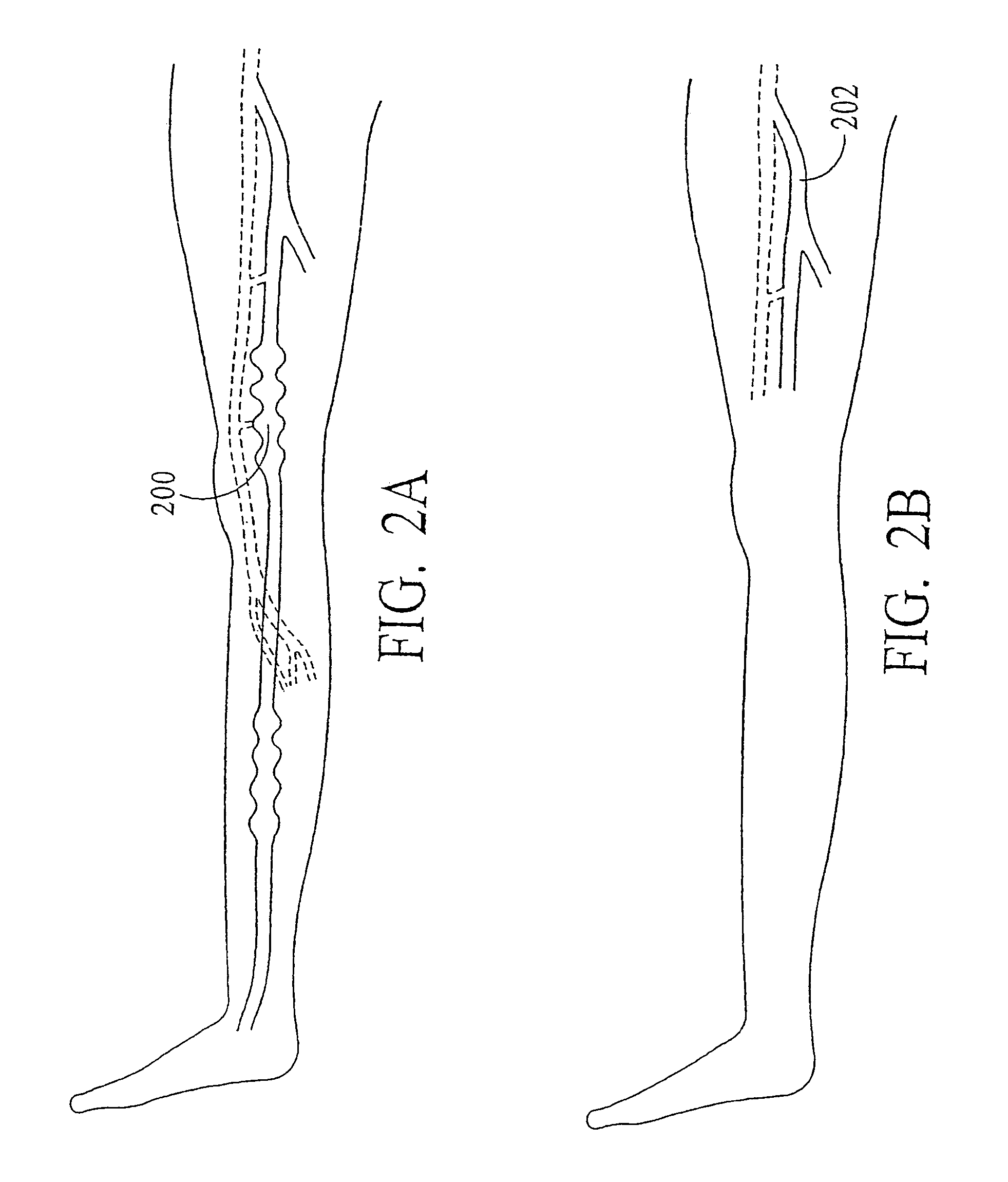
This invention is an improved method and device for treating varicose veins 200 or the greater saphenous vein 202. The method comprises the use of infrared laser radiation in the region of 1.2 to 2.2 um in a manner from inside the vessel 200 or 202 such that the endothelial cells of the vessel wall 704 are damaged and collagen fibers in the vessel wall 704 are heated to the point where they permanently contract, the vessel 200 or 202 is occluded and ultimately resorbed. The device includes a laser 102 delivered via a fiber optic catheter 300 that may have frosted or diffusing fiber tips 308, or that may be provided with a protective spacer. A motorized pull back device 104 may be used, and a thermal sensor 600 may be used to help control the power required to maintain the proper treatment temperature.

Description

RELATED APPLICATIONS[0001]This Application is a continuation-in-part of and claims the benefit of International Application Number PCT / US2003 / 035178, filed under the Patent Cooperation Treaty on Oct. 30, 2003, designating the United States of America, and titled “ENDOVENOUS CLOSURE OF VARICOSE VEINS WITH MID INFRARED LASER,” which application claims the benefit of U.S. Provisional Patent Application Ser. No. 60 / 422,566 filed Oct. 31, 2002, entitled ENDOVENOUS CLOSURE OF VARICOSE VEINS WITH MID INFRARED LASER, each of which is incorporated herein by reference in its entirety.FIELD OF THE INVENTION[0002]The present invention relates generally laser assisted method and apparatus for treatment of varicose veins, and more particularly, to an improved catheter method and apparatus to target blood vessel walls directly and with a controlled amount of the appropriate type of energy using a motorized pull-back device, and to improved methods and apparatus for substantially preventing direct ...

Claims


Application Information

Patent Timeline
Patent Type & Authority Patents(United States)
IPC IPC(8): A61B18/18A61B17/00A61B18/00A61B18/22A61B18/24A61B19/00
CPCA61B18/24A61B2017/00084A61B2018/00005A61B2018/00196A61B2018/2261A61B2019/306A61B2090/036
Inventor HENNINGS, DAVID R.GOLDMAN, MITCHEL P.WEISS, ROBERT A.TAYLOR, ERIC B.JOHNSON, DONCESPEDES, IGNACIO
Owner COOLTOUCH
Learn More