Imaging apparatus, imaging system, imaging method, and computer program

a technology of imaging apparatus and imaging method, which is applied in the field of imaging apparatus, imaging system, imaging method, computer program, etc., can solve the problems of correction error that may occur in the correction method of the conventional radiographic imaging apparatus, etc., to achieve good image, reduce correction errors, and reduce the effect of correction errors

Active Publication Date: 2009-05-12
CANON KK
View PDF33 Cites 38 Cited by
  • Summary
  • Abstract
  • Description
  • Claims
  • Application Information

AI Technical Summary

Benefits of technology

[0037]According to the present invention, there is provided a computer program which causes a computer to correct at least gain characteristics of a plurality of conversion elements for an image signal of an object, which is captured by an imaging unit having the plurality of conversion elements, using different correction signals in accordance with a plurality of radiographic modes.
[0038]According to the present invention, there is provided a computer program which causes a computer to correct at least gain characteristics of a plurality of conversion elements for an image signal of an object, which is captured by an imaging unit having the plurality of conversion elements, using different correction signals in accordance with a radiation dose to be applied to the imaging unit in order to obtain the image signal for one image.
[0040]According to the present invention, a gain of an image signal of an object which is captured by an imaging unit is corrected using different correction signals in accordance with a radiation dose to be applied to the imaging unit in order to obtain the image signal for one image. Even when image capturing is performed using an imaging unit having different gain characteristics according to the radiation dose, a good image with decreased correction errors can be acquired regardless of the radiation dose.

Problems solved by technology

Consequently, a correction error may occur in a correction method of the conventional radiographic imaging apparatus.
Consequently, a correction error may occur in the correction method of the conventional radiographic imaging apparatus.
In addition, even when the history of radiation irradiation, history of electrical field application, environmental temperature, or the like differs between general radiography (still image) and fluorography (moving image), a correction error may occur in a correction method of the conventional radiographic imaging apparatus.
These phenomena indicate that when the signal A obtained in moving image radiography is corrected by a gain correction signal suited to still image radiography, sometimes a correction error may occur.
However, these references do not describe at all the correction error caused by a difference in gain characteristics according to the radiographic mode.
More specifically, when both moving image radiography and still image radiography are performed by the conventional X-ray imaging apparatus, gain correction is not performed appropriately, and sometimes the image quality is degraded.

Method used


Image

  • Imaging apparatus, imaging system, imaging method, and computer program
  • Imaging apparatus, imaging system, imaging method, and computer program
  • Imaging apparatus, imaging system, imaging method, and computer program

Examples


first embodiment

[0059]The first preferred embodiment of the present invention will be described.

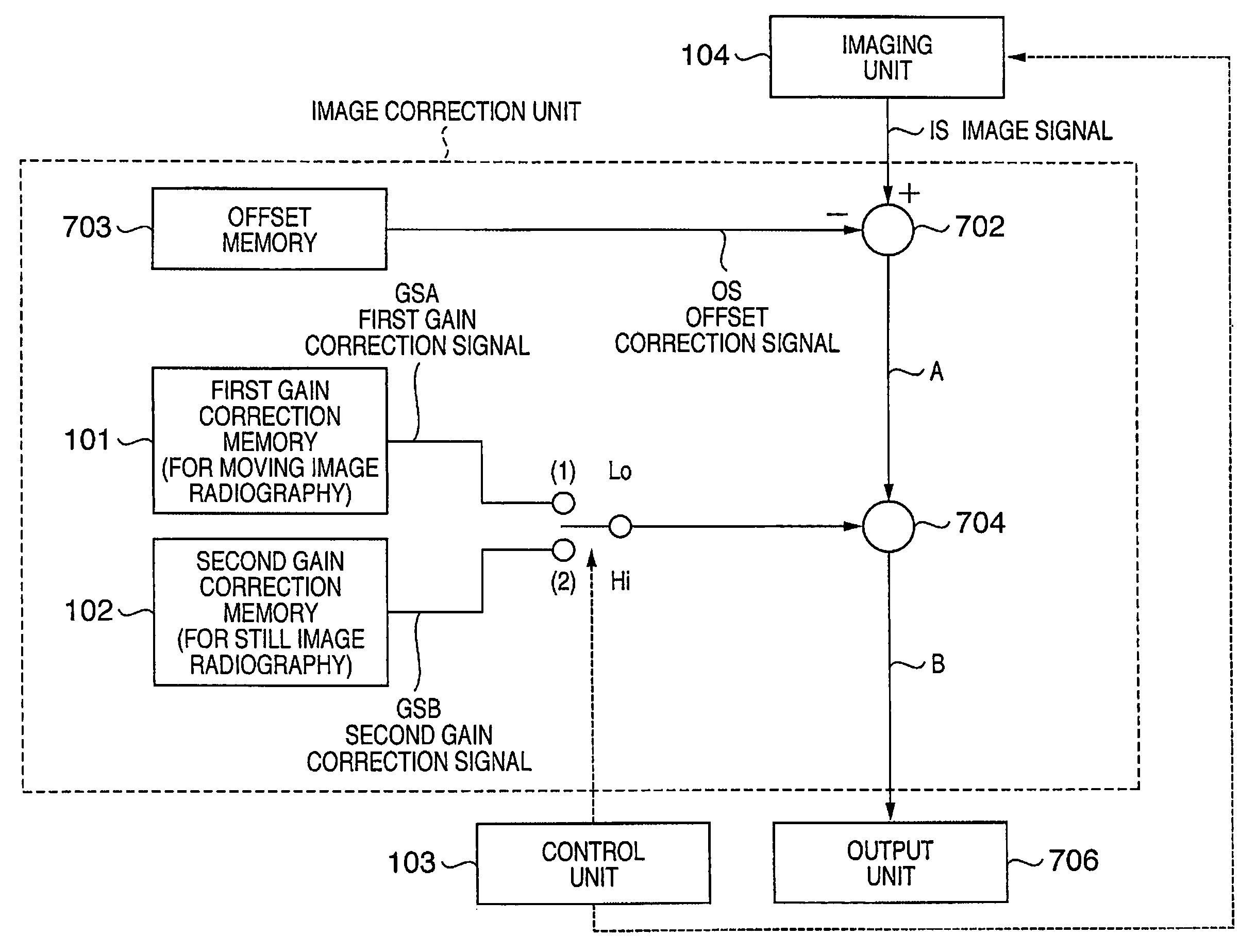
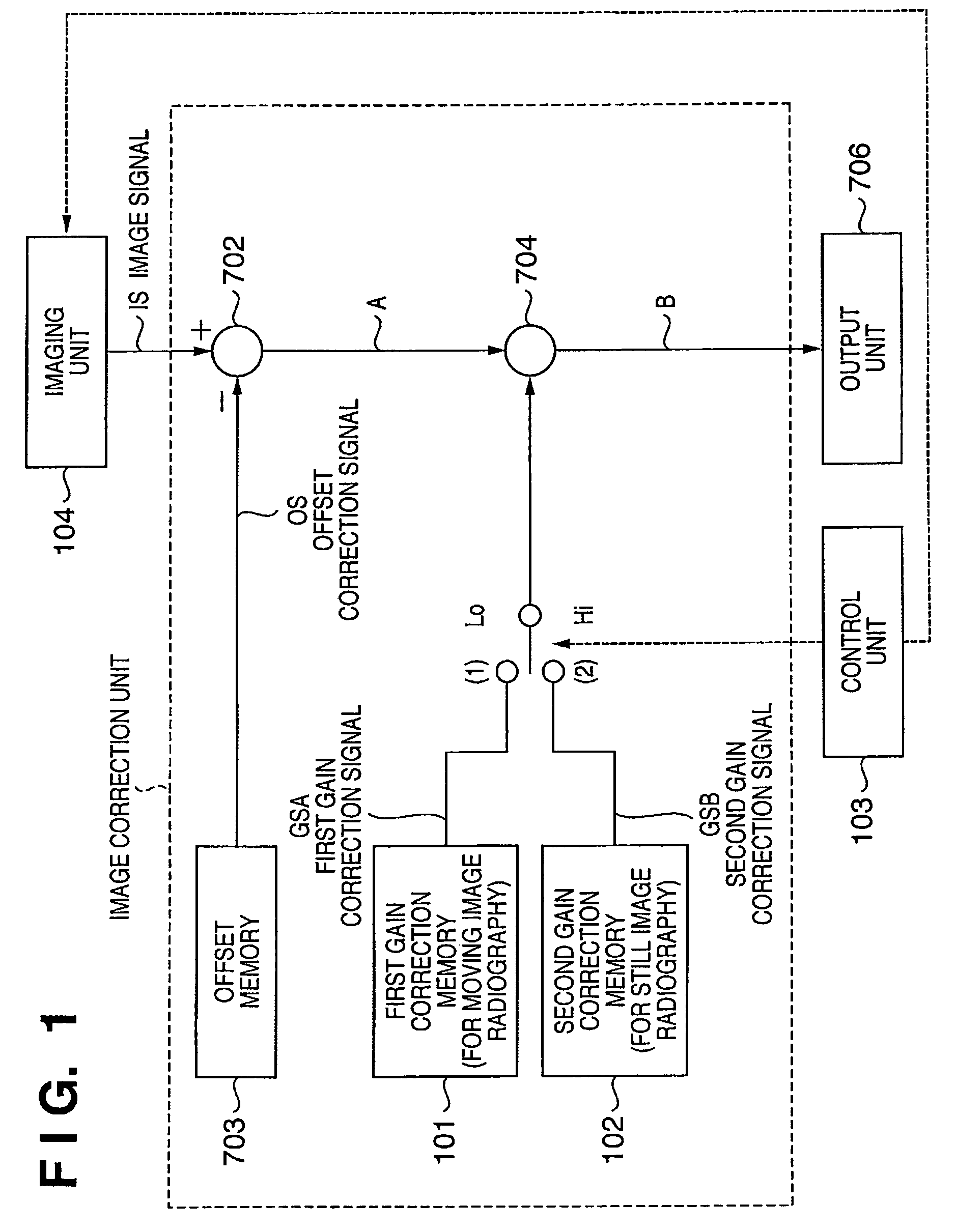
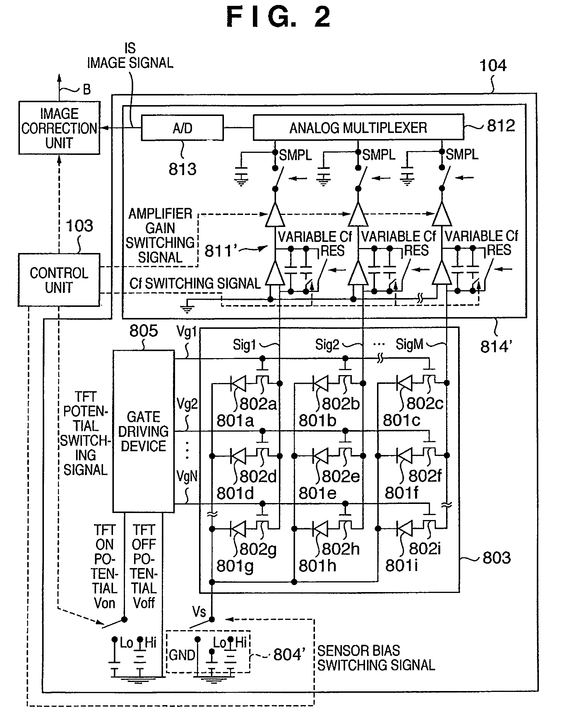
[0060]FIGS. 1 and 4 are block diagrams of the first preferred embodiment of the present invention and explain the first and second examples of the structure of an X-ray imaging apparatus which performs image correction. FIG. 2 is a circuit diagram of the first preferred embodiment of the present invention and schematically shows an example of the structure of an imaging unit which is included in the X-ray imaging apparatus. FIGS. 3 and 5 are timing charts of the first preferred embodiment of the present invention and explain the first and second examples of the operation of the X-ray imaging apparatus. FIG. 6 is a view of a preferred embodiment of the present invention and shows an example of the structure of an X-ray radiographic system which uses an X-ray imaging apparatus. In FIGS. 1 to 6, the similar constituent elements as in FIGS. 7 to 9B described above are denoted by the same reference numerals, ...

second embodiment

[0088]The second preferred embodiment of the present invention will be described.

[0089]FIG. 6 is a view of the second preferred embodiment of the present invention to show an example of the structure of a radiographic system which uses the X-ray imaging apparatus according to the first embodiment described above.

[0090]Referring to FIG. 6, an image processor 6070 is provided with the gain correcting function described above. According to the characteristic feature of the radiographic system of the second embodiment, an X-ray generating device which irradiates the target with X-rays is provided, and a control unit 103 for the image processor 6070 can control the operation of the X-ray generating device.

[0091]For example, the image processor 6070 has a microcomputer including a CPU which controls the overall X-ray imaging apparatus, a ROM which stores a control program or the like to be executed by the CPU, a work area necessary when the CPU runs the control program, and an EEPROM whic...

third embodiment

[0095]The third preferred embodiment of the present invention will be described.

[0096]FIG. 11 is a circuit diagram of the third preferred embodiment of the present invention, schematically showing an example of the structure of an imaging unit which is included in an X-ray imaging apparatus. Compared to FIG. 2 showing the first embodiment, the third embodiment differs in that an image correction unit is provided between an analog multiplexer 812 and A / D converter 813 of a reading device 814′ and the correction process described above is executed in an analog mode. An arithmetic process of the image correction unit may be executed by combining an operational amplifier. An analog memory combined with a capacitor or the like may be used as a memory means. The contents of a digital memory may be D / A-converted and operated in an analog mode. Other basic operations and definitions are same as those of the first embodiment described with reference to FIGS. 1 to 5, and a detailed descriptio...


PUM


Abstract

A correction process is performed using different gain correction signals (GSA, GSB) in accordance with radiographic modes (moving image radiographic mode / still image radiographic mode) set in an X-ray imaging apparatus, respectively. This makes it possible to acquire an image with decreased correction errors even when the X-ray imaging apparatus is configured using an imaging unit having different gain characteristics in the still image radiographic mode and moving image radiographic mode.

Description

[0001]This is continuation of international application Serial No. PCT / JP 2005-014436, filed Aug. 5, 2005.TECHNICAL FIELD[0002]The present invention relates to an imaging apparatus, imaging system, imaging method, computer program, and is particularly suitable to correct the gain of a radiographed image.BACKGROUND ART[0003]The conventional technique will be described with reference to the accompanying drawings.[0004]FIG. 7 is a block diagram showing the structure of a conventional radiographic imaging apparatus which performs image correction. FIG. 8 is a circuit diagram schematically showing the structure of a conventional imaging unit used in the radiographic imaging apparatus. Note that radiation includes X-, α-, β-, and γ-rays, and the like.[0005]As shown in FIG. 8, the imaging unit 701 used in the conventional radiographic imaging apparatus has an area sensor 803 in which pixels are arrayed in a two-dimensional matrix to perform matrix driving. The pixels comprise conversion el...

Claims


Application Information

Patent Timeline
Patent Type & Authority Patents(United States)
IPC IPC(8): H05G1/64H01L27/146H03G3/00H05G1/58A61B6/00G01T1/17G01T1/20G01T1/24H04N5/32H04N5/369H04N5/374
CPCA61B6/00A61B6/5235A61B6/585H04N5/32H04N5/3651H04N5/378H04N25/671H04N25/75
Inventor KAMESHIMA, TOSHIOENDO, TADAOYAGI, TOMOYUKITAKENAKA, KATSURO
Owner CANON KK
Why Eureka
Try Eureka