System and method for noninvasively monitoring conditions of a subject

a non-invasive monitoring and condition technology, applied in mechanical audible signalling, radiation therapy, diagnostics using light, etc., can solve the problems of limiting the spatial resolution of the measurement produced by continuous acoustic waves, and the spatial resolution of the measurement produced by a continuous acoustic wave is not as high as the measurement produced, so as to improve the oximetry and pulse oximetry based measurement

Inactive Publication Date: 2009-06-02
OR NIM MEDICAL
View PDF9 Cites 42 Cited by
  • Summary
  • Abstract
  • Description
  • Claims
  • Application Information

AI Technical Summary

Benefits of technology

[0005]The present invention utilizes the principles of ultrasound tagging of light. More specifically, the tagging of light by acoustic radiation is used to determine the optical response of a region of interest. The invention may be used, for example, to significantly improve oximetry and pulse oximetry based measurements.
[0007]It is a common goal of any optical measurement technique to be capable of providing a high resolution measurement of the local light distribution with an improved signal to noise ratio (SNR). The present invention addresses this problem by providing a novel method and system based on the principles of acoustic tagging of light, where the acoustic radiation is appropriately modulated (coded) to provide high-resolution and high-SNR measurement results.
[0008]The main idea of the present invention is based on the following understanding: The effect termed “Ultrasound Tagging of Light” (UTL) is based on the interaction of acoustic waves with the same tissue volume that is being probed by light. This interaction causes the light wave to be modulated, or tagged, with the characteristics of the acoustic wave (i.e. frequency, phase). As the propagation of acoustic waves in tissue is relatively slow (about 1500 m / sec in soft tissue), the location of the interaction of light with the acoustic radiation can be determined. The efficiency and power of the interaction of the acoustic waves with the medium affects the spatial and temporal resolution and the SNR of the measurement. There are three possible modalities for the generation of acoustic waves, a continuous wave (CW), a short burst of waves (SB), and a pulse. Operation with continuous waves produces a higher SNR. When a continuous acoustic wave (at a predetermined frequency range) interacts with light, and light is collected throughout the full propagation of the acoustic waves, a higher acoustic energy is available for the interaction, thereby increasing the signal. In addition, the spectral bandwidth of the continuous acoustic wave can be very narrow, thus reducing noise bandwidth. Thereby the SNR is greatly improved. However, the spatial resolution of a measurement produced with continuous acoustic waves is not as high as a measurement produced with short bursts or pulses of acoustic waves. This reduced spatial resolution is particularly limiting when the measurement geometry calls for propagation of acoustic waves essentially parallel to the direction of light propagation. As for the use of short bursts of waves and pulses, this provides better spatial resolution, but the acoustic energy of the interaction is lower and the bandwidth is wider as compared to those of a continuous wave mode, resulting in reduced SNR.
[0009]There is accordingly a need in the art for a measurement technique which can achieve both high spatial resolution and high SNR. The present invention solves this problem by utilizing generation of continuous acoustic waves (and therefore improving the SNR), where the continuous acoustic wave is a modulated (coded) signal characterized by a narrow autocorrelation function, thereby improving the spatial resolution.
[0013]The present invention thus provides for a 3D mapping of the light distribution in a turbid medium, obtaining a non invasive means for collecting data about the structure and composition of the turbid medium. The use of a continuous acoustic signal utilizes the acoustic and light energy more efficiently, and lower acoustic and optical signals can be used while maintaining the desired SNR. Thus, the light levels and acoustic levels introduced into the subject are safer.
[0025]In some embodiments of the present invention, multiple light sources and / or detectors and / or acoustic sources may be used. Such configurations improve the spatial resolution of the measurements and enable the mapping of a larger volume of the medium. For the purposes of the present invention, when multiple acoustic sources (i.e. multiple acoustic waves) are used, all acoustic sources can use either different frequency ranges or the same frequency range, as long as the modulating sequences of the different acoustic sources have zero or near zero cross correlation. When the electromagnetic response signal is detected and decoded, each acoustic beam tagging effect can be estimated separately by correlating the respective received signal with the original modulating sequence for this acoustic source. The contribution of other acoustic sources to such a correlation is negligible given the zero or near zero cross correlation between the sequences, as will be described below.

Problems solved by technology

However, the spatial resolution of a measurement produced with continuous acoustic waves is not as high as a measurement produced with short bursts or pulses of acoustic waves.
This reduced spatial resolution is particularly limiting when the measurement geometry calls for propagation of acoustic waves essentially parallel to the direction of light propagation.

Method used


Image

  • System and method for noninvasively monitoring conditions of a subject
  • System and method for noninvasively monitoring conditions of a subject
  • System and method for noninvasively monitoring conditions of a subject

Examples


Embodiment Construction

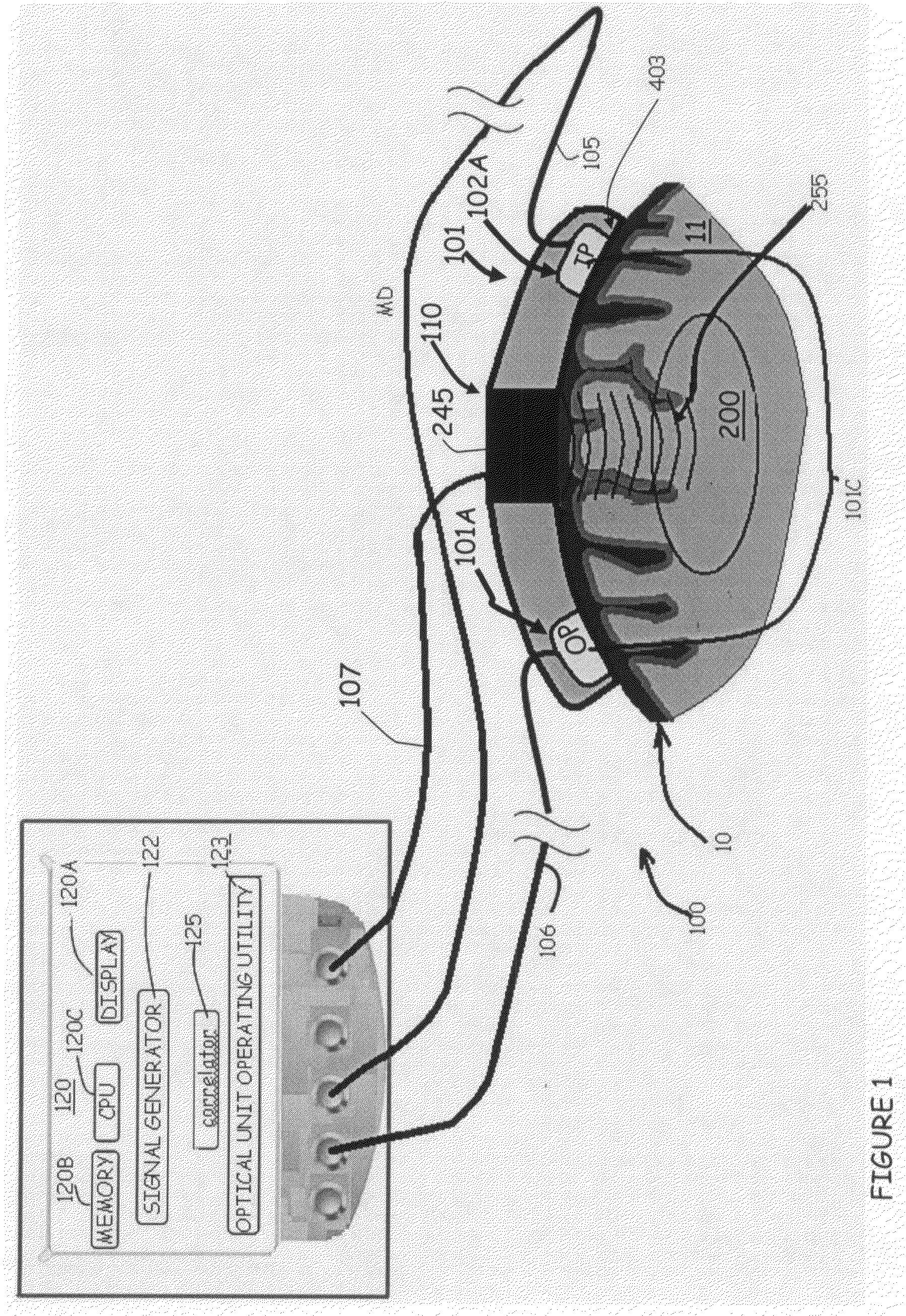
[0037]Reference is made to FIG. 1 illustrating schematically a specific but not limiting example of a measurement system, generally designated 100, configured and operable according to the invention for non-invasive determination of one or more parameters (properties of tissue components) of a subject, particularly a human or animal body. The parameter(s) to be determined may include oxygen saturation level, or values / levels of various other parameters such as the concentration of an analyte in the patient's blood, or the perfusion of an analyte / metabolite in tissues. The values of these parameters are derived from the light distribution in a region of interest 200 as will be described below.

[0038]System 100 includes such main constructional parts as a measurement unit 101 and a control unit 120. Measurement unit 101 includes an optical or electromagnetic unit (module) 101C and an acoustic unit (module) 110. Optical module 101C includes an illumination assembly 101A and a light dete...


PUM


Abstract

A method and system are presented for use in determining one or more parameters of a subject. A region of interest of the subject is irradiated with acoustic tagging radiation, which comprises at least one acoustic tagging beam. At least a portion of the region of interest is irradiated with at least one electromagnetic beam of a predetermined frequency range. Electromagnetic radiation response of the at least portion of the region of interest is detected and measured data indicative thereof is generated. The detected response comprises electromagnetic radiation tagged by the acoustic radiation. This enables processing of the measured data indicative of the detected electromagnetic radiation response to determine at least one parameter of the subject in a region corresponding to the locations in the medium at which the electromagnetic radiation has been tagged by the acoustic radiation, and outputting data indicative of the at least one determined parameter.

Description

FIELD OF THE INVENTION[0001]This invention relates to a method and system for monitoring a subject's condition, based on scattered light distribution through turbid media. The invention is particularly useful in medical applications.BACKGROUND OF THE INVENTION[0002]Non invasive monitoring and imaging using non-ionizing radiation, allows medical professionals to diagnose and monitor a patient without invasive surgeries, or even without drawing blood. Pulse oximetry is one such revolutionizing technology, where non invasive monitoring of blood oxygenation using light has replaced blood gas analysis. Thus, pulse oximetry has become a gold standard monitor in every clinical setting, and has saved millions of lives.[0003]During non-invasive monitoring, the concentration of certain chromophores (such as oxygenated and deoxygenated hemoglobin in oximetry) is calculated by detecting light that escapes the tissue, determining the optical properties of the tissue, and deriving therefrom the c...

Claims


Application Information

Patent Timeline
Patent Type & Authority Patents(United States)
IPC IPC(8): A61B5/05
CPCA61B5/0059A61B5/0097G01N21/1702A61B5/1455G01N21/1717G01N21/4795G01N21/49G01N2021/1727
Inventor METZGER, YAACOVROKNI, MICHALPERY-SHECHTER, REVITAL
Owner OR NIM MEDICAL
Why Eureka
Try Eureka