Auto-protected power modules and methods

a power module and auto-protection technology, applied in the direction of electric motor control, vehicle heating/cooling devices, transportation and packaging, etc., can solve the problems of insufficient suitability to meet various needs, choppy or stepwise level of control, and large latency period, etc., to achieve simple and convenient manufacturing, improve performance, and reduce the effect of cos

Inactive Publication Date: 2009-06-02
CARTER GRP INC
View PDF7 Cites 74 Cited by
  • Summary
  • Abstract
  • Description
  • Claims
  • Application Information

AI Technical Summary

Benefits of technology

[0006]In accordance with the principles of the present invention, variable speed motor power modules for powering an electric direct current variable speed motor may be provided. The power module may be configured to capitalize on the use of analog circuit components in implementing power module functionality. In some circumstances, such techniques may enhance the performance, simplicity, and manufacturing (e.g., assembly of analog components on a printed circuit board may be less expensive than fabricating an integrated circuit). If desired, however, the power modules may use combinations of digital and analog components. If such combinations are used, it may be desired to primarily use the analog circuit components in assembling the power module.

Problems solved by technology

A resistive divider operates by modulating the power provided to the electric motor by a constant or adjustable amount, resulting in a choppy or stepwise level of control.
The speed of the electric motor has a linear relationship with the voltage supplied to the motor, hence the term “linear.” These systems tend to be characterized by an undesirably large latency period, i.e., the period between detection and correction of the desired motor speed.
Known techniques for implementing linear power modules or implementing systems that use linear power modules (e.g., HVAC systems) have sometimes been found to be inadequate in suitably meeting various needs such as efficiency, noise reduction, simplicity in design, cost of production, responsiveness, etc.

Method used


Image

  • Auto-protected power modules and methods
  • Auto-protected power modules and methods
  • Auto-protected power modules and methods

Examples


Embodiment Construction

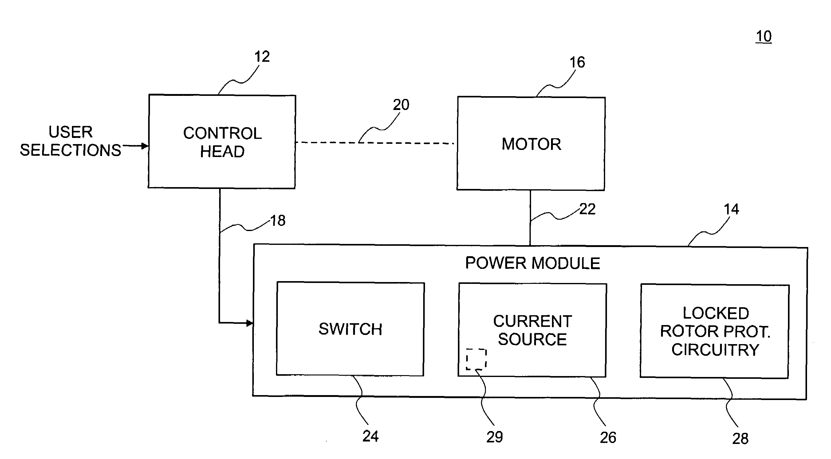
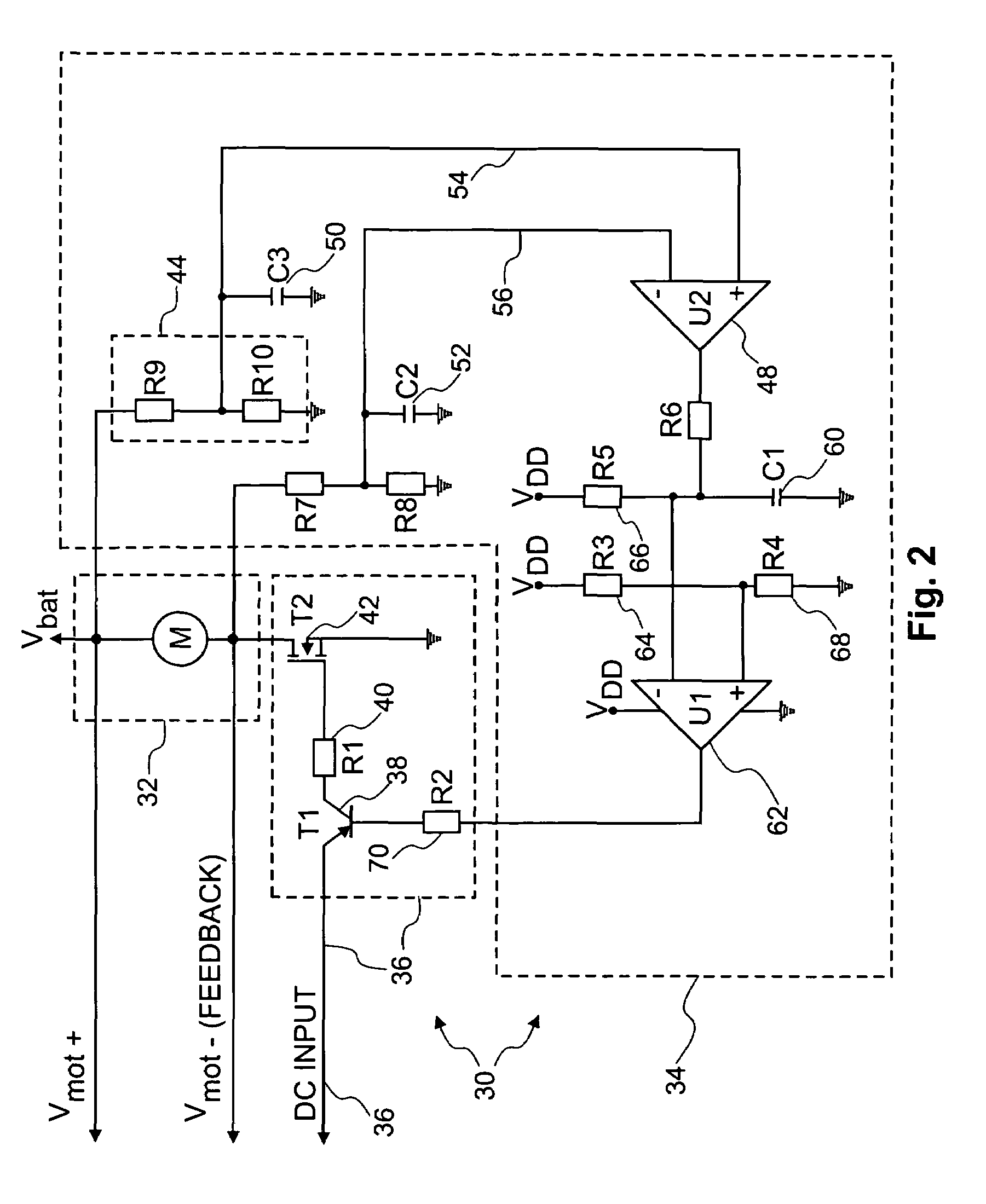
[0027]Analog circuit arrangements may be configured to provide a power module that may provide advantages in operation, manufacturing, efficiency, and technical simplification. With reference now to FIG. 1, system 10 may be a system for operating a variable speed electric motor such as an HVAC system of an automobile. System 10 may include control head 12, power module 14, and motor 16. Motor 16 may include circuitry in addition to an electric motor that is incorporated therein. Control head 12 may be an electronic controller that is configured to receive user selections with respect to the motor speed of motor 16. Typically, discrete stepwise user-selectable speed settings are available. A control head or electric controller is a typical part of conventional control systems for electric motors and are known to those skilled in the art.

[0028]Control head 12 is shown to have connection 20 with motor 16 (e.g., an electrical connection that does not pass through power module 14). Dashe...


PUM


Abstract

A linear power controller system may be implemented that includes locked-rotor protection circuitry that is primarily assembled using analog circuit components. The locked rotor protection circuitry may be part of a power module in the system. The power module may be a switched power source that includes temperature circuit. A control loop may be established in the system to maintain the voltage across a motor that is driver by the power module. Circuitry for establishing a close loop with a motor may be positioned in a control head in the system or in a power module in the system. Temperature protection circuitry may be integrated into a current source in the power module to provide automatic thermal shutdown of the current source. The linear power module may specifically include analog circuitry that is arranged to establish a control loop with the motor.

Description

BACKGROUND OF THE INVENTION[0001]The present invention is generally related to control systems for variable speed electric motors, and more particularly, to power modules in such control systems.[0002]Presently, electronic controllers are typically designed for 12 V or 24 V electrical systems such as those used in automotive applications. Electronic controllers in automobiles are typically attached to dashboards, seat bottoms, rear side of the passenger compartment, or the like by being screwed into designated place(s).[0003]Present-day electric motors, such as those used in heating, ventilating, and air conditioning (HVAC) systems of automobiles, are controlled mainly using switch-mode technology, in which a fixed DC power supply is switched on and off with a predetermined switch frequency and pulse width modulated switch-on time as needed to control the motor speed. In the United States, the motor control technology has been implemented primarily by use of a resistive divider (e.g...

Claims


Application Information

Patent Timeline
Patent Type & Authority Patents(United States)
IPC IPC(8): H02H7/00H02P29/02
CPCH02P29/02B60H1/00428Y02T10/88
Inventor IVANKOVIC, MLADEN
Owner CARTER GRP INC
Why Eureka
Try Eureka