
Thermally reflective encapsulated phase change pigment

a phase change pigment and thermal conductivity technology, applied in the field of micro-sized, lightweight thermally reflective phase change materials, can solve the problems of limited thermal mass of current phase change pigments, such as outlast's thermal additive powder, and no inherent ability to reflect any of this solar loading, and achieve the effect of reducing the potential for phase change materials to rapidly saturate thermally

Inactive Publication Date: 2009-06-09
NAVY U S A AS REPRESENTED BY THE SEC OF THE THE
View PDF6 Cites 8 Cited by
  • Summary
  • Abstract
  • Description
  • Claims
  • Application Information

AI Technical Summary

Benefits of technology

"The patent text describes a method to improve the performance of phase change materials by coating them with a metallic coating that can reflect heat and make them electrically conductive. This can help to prevent the materials from overheating and can also make them more efficient in their phase change process. The coating can also be applied to make the materials multifunctional, with an added layer of electrically conducting material."

Problems solved by technology

A few of the drawbacks to the conventional phase change materials include the fact that solar loading can be attributed to roughly ⅓ to ⅔ of the total heating of an outdoor structure.
Current phase change pigments, such as Outlast's thermal additive powder, have limited thermal mass and no inherent ability to reflect any of this solar loading.
They also have extremely low thermal conductivity, which creates the potential for the phase change materials to rapidly saturate thermally.
Clothing utilizing conventional phase change materials can only regulate temperature by means of storing and releasing the thermal energy that a person's body produces.
It is not very effective at reflecting body heat back to prevent its escape.
It is also not effective in reducing the effects of solar heating in warm weather apparel.
A material with very low thermal conductivity will not be very effective in transferring heat from critical electronic component.
This hinders their use as practical heat sinks in both commercial and military electronics.
Microencapsulated phase change materials are typically composed of a wax and an encapsulating polymer shell, both of which are highly susceptible to degradation by high temperatures.
This works well for larger parts but it is almost impossible to simultaneously coat millions of micro particles.

Method used


Image

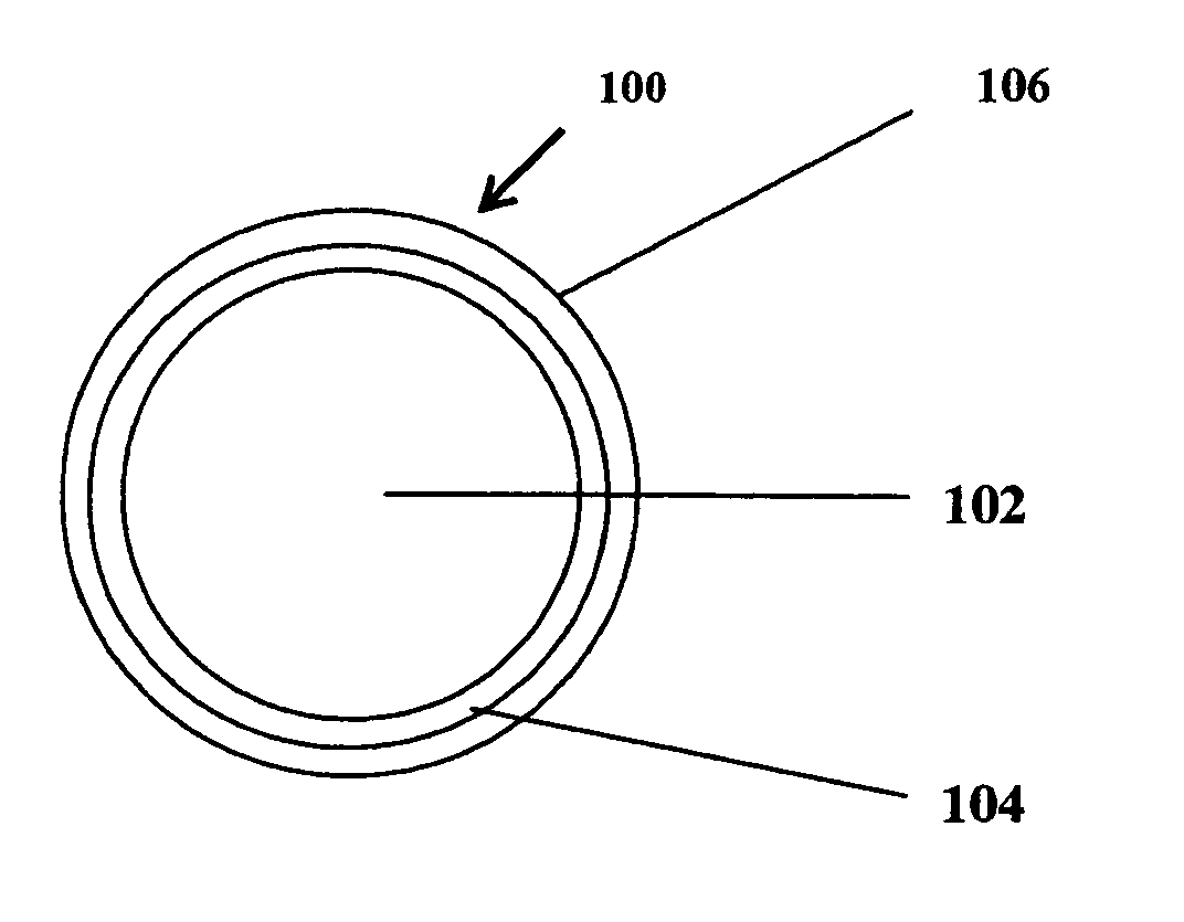
  • Thermally reflective encapsulated phase change pigment
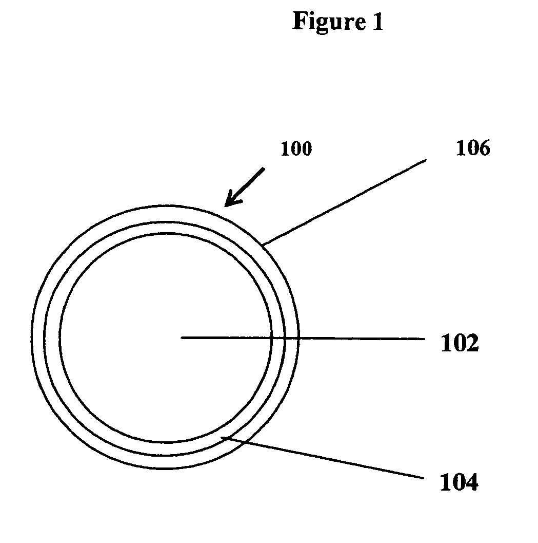
  • Thermally reflective encapsulated phase change pigment

Examples


example

[0064]This example demonstrates electroless plating with a monolayer coating of silver on a 100 g particulate sample of encapsulated phase change pigment material with a density of 0.9 g / cc and particle diameter of 22.0 microns. The particulate phas change material used was Frisby's Thermosorb TO-83 material where the core material was octodecane wax. Silver thickness on each particle was 900 angstroms. Volume of one particle was 5.57528×10⁻⁹ cm3, surface of one particle was 1.52×10⁻⁵ cm2, sample volume was 111.11 cm3, number of particles in the sample was 1.99×10¹⁰, volume of one coated particle was 5.71325×10⁻⁹ cm3, volume of one particle coating was 1.3797×10⁻¹⁰ cm3, volume of coating sample was 2.746 cm3, and weight of silver was 28.005 g.

[0065]Procedure of coating the particulate encapsulated phase change material with silver from 44.17 g of silver nitrate (AgNO3), was as follows:[0066]a. A 2000 ml beaker, which has been cleaned with nitric acid, was charged with 888.88 ml of d...


PUM

PropertyMeasurementUnit
diameteraaaaaaaaaa
thicknessaaaaaaaaaa
diameteraaaaaaaaaa

Abstract

This invention pertains to particulate thermally reflective phase change material that includes an encapsulated phase change material coated with a thermally reflective layer.

Description

BACKGROUND OF THE INVENTION[0001]1. Field of the Invention[0002]This invention pertains to micro-sized, lightweight thermally reflective phase change material that is electrically conductive and is highly efficient at regulating temperature.[0003]2. Description of Related Art[0004]Phase change materials were first developed for astronauts' space gear to protect them from the extreme heat and cold experienced during space expeditions. These materials consist of paraffin waxes that are capable of storing large amounts of latent thermal energy through the process of phase changing. Conventional phase change materials offer an order-of-magnitude increase in thermal storage capacity over non-phase change based materials with the added benefit of nearly isothermal discharge. This allows the storage of large amounts of latent thermal energy without significantly changing the environment around the encapsulated phase change materials. The pigment particles are roughly 1-100 microns in diame...

Claims


Application Information

Patent Timeline
Patent Type & Authority Patents(United States)
IPC IPC(8): B32B5/16
CPCC01G3/00C01G19/04C09C1/66C09K5/063C01P2004/61C01P2004/62C01P2004/84Y10T428/261C01P2006/40Y10S428/913Y10T428/2991C01P2006/10
Inventor BELLEMARE, JAMES V.
Owner NAVY U S A AS REPRESENTED BY THE SEC OF THE THE
Learn More