Distributed arbitrary waveform generator

Inactive Publication Date: 2009-06-09
UNIVERSITY OF ROCHESTER
View PDF3 Cites 14 Cited by
  • Summary
  • Abstract
  • Description
  • Claims
  • Application Information

AI Technical Summary

Benefits of technology

[0008]Secondly, it is desirable to use an individual pulse generator in each tap. Since narrow pulses are generated locally, only relatively low-speed trigger signal needs to be distributed to each tap. Hence the trigger distribution network does not require large bandwidth, and can be designed for timing control only. In turn, because the timing control requirement is no longer applied, the pulse combining block can be designed to have low loss and large bandwidth. Such a divide-and-conquer approach removes the constraints of delay-bandwidth trade-off in other wideband pulse processing circuits, such as distributed transversal filter. In a DAWG, circuit complexity is traded with the bandwidth. In the integrated circuit implementation, circuit complexity can be easily accommodated due to the good integration capability, especially in CMOS technologies. Inc

Problems solved by technology

In conventional AWG implementations based on time interleaving, the functions of waveform synthesis and pu

Method used


Image

  • Distributed arbitrary waveform generator
  • Distributed arbitrary waveform generator
  • Distributed arbitrary waveform generator

Examples


Example

[0023]Preferred embodiments of the present invention will be set forth in detail with reference to the drawings, in which like reference numerals refer to like elements throughout.

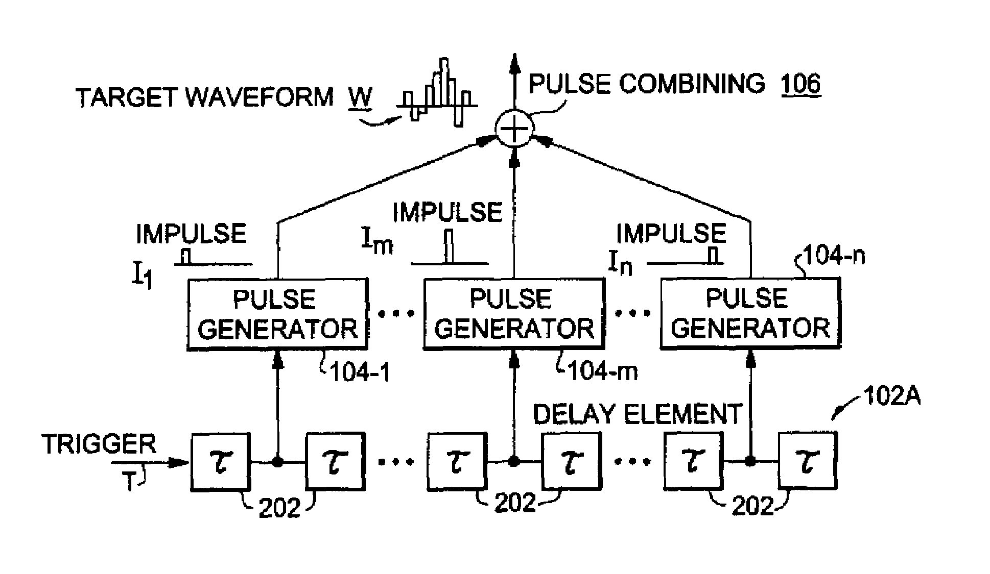
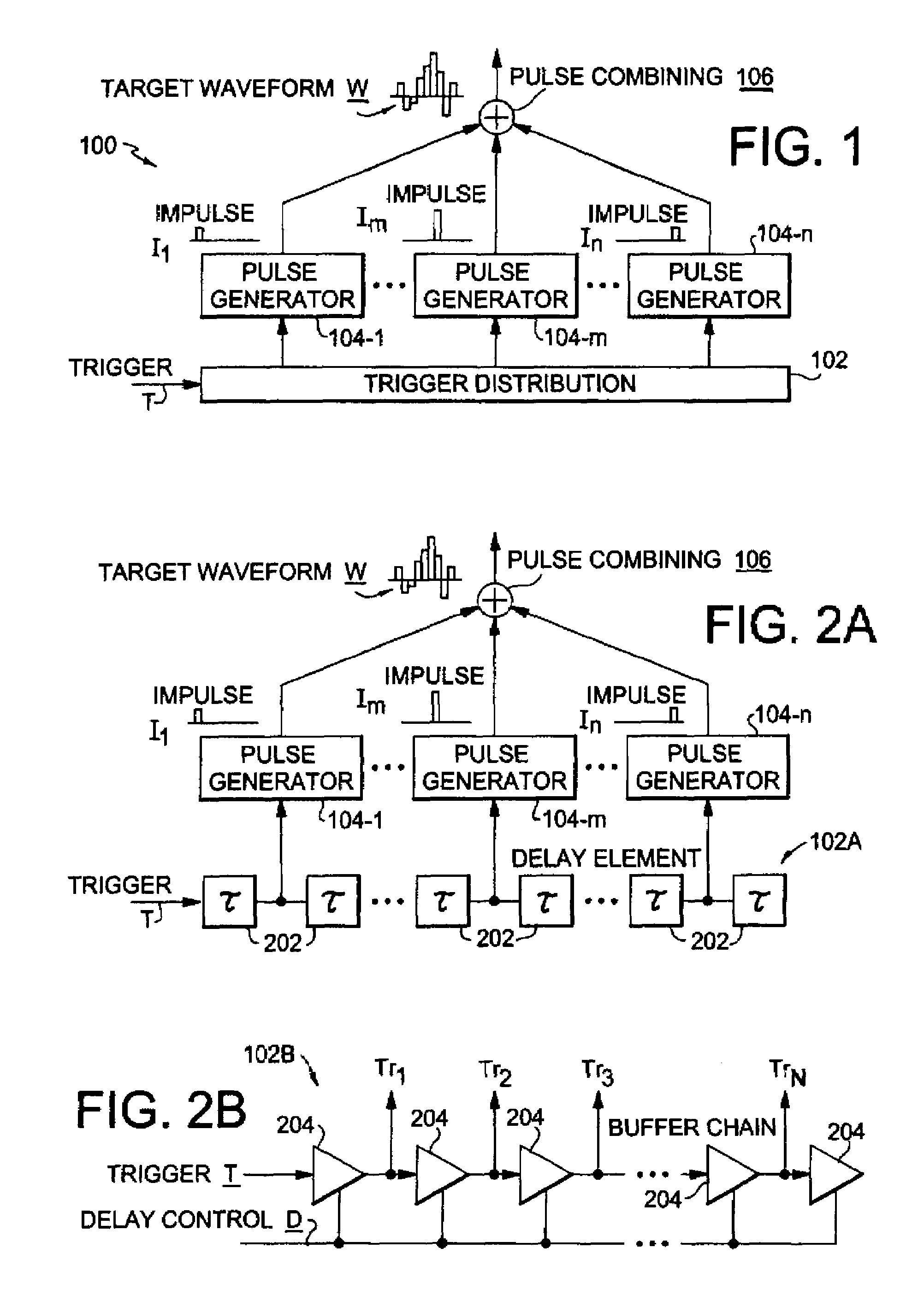
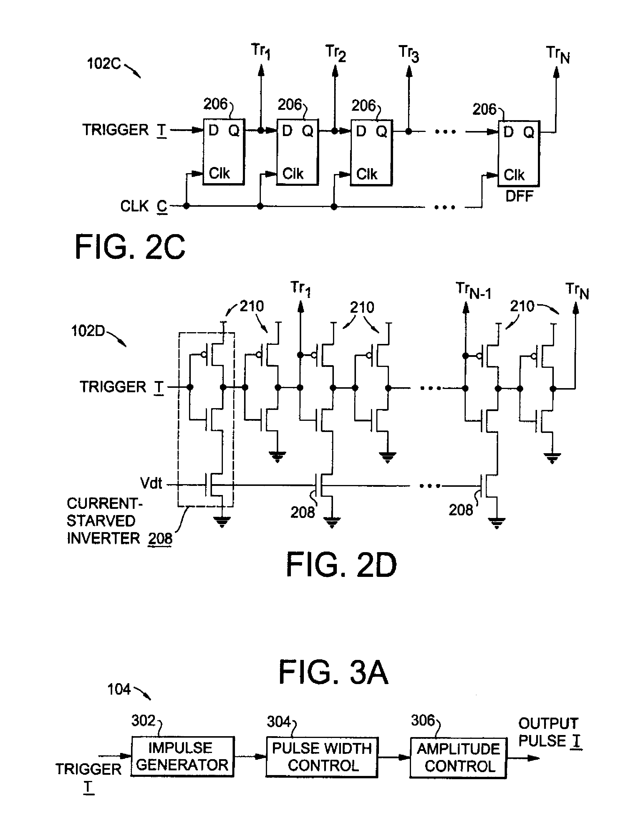
[0024]FIG. 1 is a block diagram showing a distributed arbitrary waveform generator (DAWG) 100. A trigger signal T is input to a trigger distribution network 102, whose design will be explained below. The trigger distribution network 102 distributes the trigger signal T to a plurality of pulse generators 104-1, . . . 104-m, . . . 104-n, which produce impulses I1, . . . Im, . . . In shaped in a manner to be described below. The pulses are combined by a pulse combining circuit 106 to produce the target waveform W.

[0025]Various implementations of the trigger distribution network 102 are shown in FIGS. 2A-2D as 102A, 102B, 102C and 102D. The trigger distribution network can be implemented as a delay line 102A with delay elements 202, as shown in FIG. 2A. Since it does not require large bandwidth, an active dela...


PUM


Abstract

A distributed arbitrary waveform generator (DAWG) synthesizes the target waveform using a series of narrow pulses generated by a number of pulse generators. To achieve this, it uses an input trigger signal to control all the pulse generators, each of which generates a narrow pulse (impulses) at a specific sample time, and then all the impulses are combined to generate the output waveform. The input trigger signal is distributed to each pulse generator by a trigger distribution network. Impulses generated by pulse generators can be tuned in both pulse amplitude and width, and the spacing between them can be tuned by the trigger distribution network. Therefore the waveforms generated are completely reconfigurable.

Description

REFERENCE TO RELATED APPLICATION[0001]The present application claims the benefit of 60 / 841,546, filed Sep. 1, 2006, whose disclosure is hereby incorporated by reference in its entirety into the present disclosure.FIELD OF THE INVENTION[0002]The present invention is directed to an arbitrary waveform generator and more particularly to such an arbitrary waveform generator which uses distributed circuit architecture.DESCRIPTION OF RELATED ART[0003]Wideband waveform generation is a critical function in modern communication and instrumentation systems. In high-speed test and measurement applications, an arbitrary waveform generator (AWG) is an indispensable time-domain instrument, and it is widely used to generate various waveforms in ultrafast phenomenon experiments across all major scientific and technological domains. For example, sub-nanosecond pulses with a variety of waveforms are needed to modulate the laser beam in inertial-confinement fusion (ICF) experiments, as taught in M. D. ...

Claims


Application Information

Patent Timeline
IPC IPC(8): H03M1/66
CPCG06F1/022H03K4/026H03K5/133H03K5/14H04B1/7174
Inventor WU, HUIZHU, YUNLIANGZUEGEL, JONATHAN D.MARCIANTE, JOHN R.
Owner UNIVERSITY OF ROCHESTER
Why Eureka
Try Eureka