
Electrospinning of fine hollow fibers

a hollow fiber and electropinning technology, applied in the field of electropinning nanofibers, can solve the problems of difficult to create hollow nanofibers of long length using prior art methods, significant and well-known limitations of this approach,

Inactive Publication Date: 2009-08-18
UNIV OF WASHINGTON
View PDF15 Cites 51 Cited by
  • Summary
  • Abstract
  • Description
  • Claims
  • Application Information

AI Technical Summary

Benefits of technology

The patent describes a method for making nanofibers using electrospinning, which involves using a spinneret to create a jet of fluid that is then collected on a collector. The method can create fibers with a core-sheath structure, a composite tubular structure, or a ceramic tubular structure. The process involves using a conductive collector and applying a high voltage to induce electrospinning. The first fluid used is a polymer solution that may contain a polymer, a solvent, and a sol-gel precursor. The second fluid used is an oil, such as mineral oil or olive oil. The as-spun fibers can be soaked in an alkane to remove the core material to produce a hollow, composite fiber. The method can also involve using a polymer solution or a conjugated polymer solution as the second fluid. The technical effects of this patent are the ability to create nanofibers with a variety of structures using electrospinning, which can be useful in various fields such as electronics, sensors, and biomedical applications.

Problems solved by technology

The elongation by bending instability results in the formation of uniform fibers that may typically have nanometer-scale diameters.
Prior art techniques have used self-assembly methods to build nanotubes from organic building blocks, although there are significant and well-known limitations to this approach.
In particular, it is difficult to create core-sheath and hollow nanofibers of long length using prior art methods due to interconnections between fibers formed during the coating and etching steps.

Method used


Image

  • Electrospinning of fine hollow fibers
  • Electrospinning of fine hollow fibers

Examples


example 1

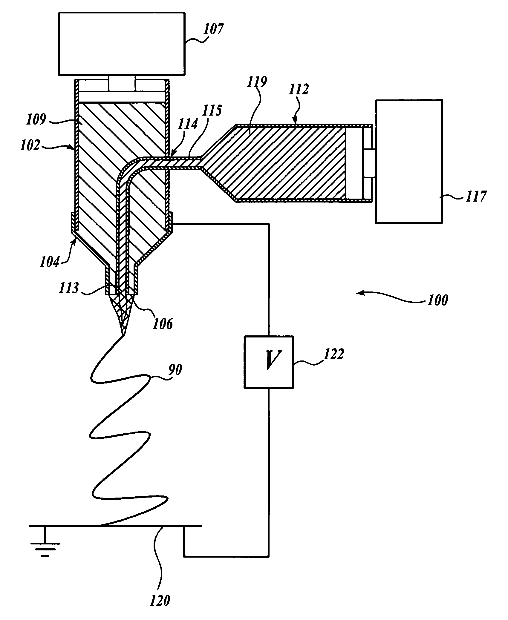
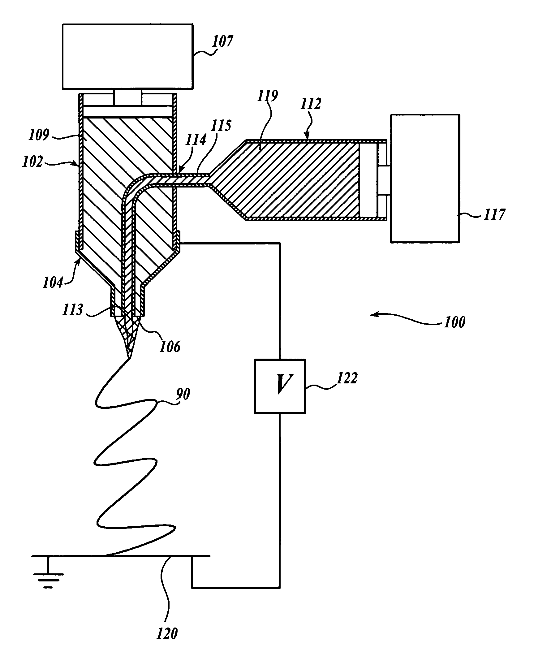
[0022]In this example of the present invention, hollow fibers of ceramic / polymer composite—in the illustrative example, a TiO2 / poly(vinyl pyrrolidone) (PVP) composite or pure ceramic nanofibers—were produced utilizing the apparatus 100 shown diagramatically in the figure. In particular, a spinneret having two coaxial apertures was fabricated by inserting a polymer-coated silica capillary 114 with an inner diameter of 75 or 100 microns and an outer diameter of 200 microns into a stainless steel needle 104 having an inner bore diameter of 450 microns, such that the distal end 113 of the capillary 114 is substantially concentric with the bore of the stainless steel needle 104. The needle 104 was hosted on a first plastic syringe 102 and the silica capillary 114 penetrated the wall of the first plastic syringe 102 and connected to a second plastic syringe 112. (The joints were sealed with an epoxy.) A polymeric solution 109 was provided in the first syringe 102, the solution consisting ...

example 2

[0031]By modifying the mineral oil core fluid 119 with various precursors, hollow nanofibers containing different functional components may be fabricated. For example, hollow nanofibers of titania containing iron oxide nanoparticles were obtained by feeding a dilute, oil-based ferrofluid to the core capillary 114, followed by alkane (e.g. octane) extraction of the oil phase. The resultant nanofibers were magnetically active. Alternatively, by adding tin isopropoxide to the oil core fluid, hollow titania nanofibers with tin oxide nanoparticles coating their inner surfaces have also been fabricated.

[0032]In order to extend the utility of composite and ceramic hollow nanofibers in applications, such as catalyst supports, optical waveguides, and nanofluidic devices, selective modification and differentiation of the inner and / or outer surfaces are highly desirable. Derivatizing the surfaces of these hollow nanofibers with different functional groups changes the surface chemistry, thereby...

example 3

[0042]In another application of the present invention, the two-capillary, core-sheath, electrospinning process provided a novel method for producing electrospinning fibers of conjugated polymers. Conjugated polymers are important for their unique combination of electronic, optical, and mechanical properties. Nanowires or nanofibers made of conjugated polymers present an ideal system for studying charge transport and luminescence in one-dimensional systems and hold promise as the building blocks for nanoelectronics. However, conventional electrospinning requires the use of an appropriate solvent and polymer system to prepare solutions exhibiting the desired viscoelastic behavior. In particular, the traditional setup for electrospinning is not easily applied to polymers with limited solubilities (e.g., conjugated polymers) or low molecular weights. One prior art strategy for improving the spinnability of conjugated polymers is to blend these polymers with other spinnable polymers in s...


PUM

PropertyMeasurementUnit
temperatureaaaaaaaaaa
diameteraaaaaaaaaa
diameteraaaaaaaaaa

Abstract

A method for electrospinning nanofibers having a core-sheath, tubular, or composite structure is disclosed. The process uses a spinneret having first and second capillaries that channel first and second fluids in the spinneret, the second capillary surrounding the first. A high voltage is applied between the spinneret and a spaced conductive collector. In one embodiment, the first fluid is a mineral oil and the second fluid is a polymeric solution that may include a polymer, a catalyst, a solvent, and a sol-gel precursor. The as-spun nanofiber includes an oil core and a composite sheath. The oil may be removed to produce a composite tubular fiber or the polymer and oil may be removed by calcination to produce a ceramic tubular fiber. In other embodiments, miscible fluids are used to produce porous nanofibers, selected additives functionalize the surfaces of the nanofibers and / or conjugated polymers are used.

Description

STATEMENT OF GOVERNMENT LICENSE RIGHTS[0001]The U.S. Government has a paid-up license in this invention and the right, in limited circumstances, to require the patent owner to license others on reasonable terms as provided for by the terms of Grant No. F49620-01-1-0358 awarded by the AFOSR (Air Force Office of Scientific Research) and / or Grant No. DMR-9983893 awarded by the NSF (National Science Foundation).FIELD OF THE INVENTION[0002]The present invention is directed to electrospinning nanofibers and, in particular, to methods for producing nanofibers having a core-sheath, hollow, or porous structure.BACKGROUND OF THE INVENTION[0003]Electrospinning is a versatile method for generating very thin fibers made of polymers, ceramics, metals, carbon, and / or composite materials. A somewhat similar technique called electrospray can be used to produce a micro / nanometric jet that breaks up to give rise to an aerosol of charged droplets. Electrospray has a proven ability to generate monodispe...

Claims


Application Information

Patent Timeline
Patent Type & Authority Patents(United States)
IPC IPC(8): D01D5/08D01D5/24D01D5/34D01F9/08H05B7/00
CPCB82Y30/00D01F1/10C04B35/624C04B35/6264C04B35/62675C04B35/62849C04B35/62876C04B35/62892C04B35/63404C04B35/63408C04B35/63432C04B35/63444D01D5/0069D01D5/24D01D5/34C04B35/62259C04B2235/3272C04B2235/3289C04B2235/3293C04B2235/408C04B2235/441C04B2235/483C04B2235/5284
Inventor XIA, YOUNANLI, DAN
Owner UNIV OF WASHINGTON
Learn More