Heat-resistant electret condenser microphone

a condenser microphone and heat-resistant technology, applied in the field can solve the problems of increased unfavorable pb-free reflow temperature, etc., and achieve the effects of reducing the restrictions on handling in the attachment of electret condenser microphones, improving thermal resistance performance, and reducing the cost of the microphone itsel

Inactive Publication Date: 2009-09-15
PANASONIC CORP
View PDF12 Cites 1 Cited by
  • Summary
  • Abstract
  • Description
  • Claims
  • Application Information

AI Technical Summary

Benefits of technology

[0023]The invention is applied to an electret condenser microphone which is often used in an information communication equipment, and can provide an electret condenser microphone in which the performances, particularly the thermal resistance performance are improved, restrictions on handling in attachment of the electret condenser microphone are mitigated, and the convenience is enhanced.

Problems solved by technology

However, a usual electret condenser microphone does not have thermal resistance against the Pb-free reflow temperature. FIG. 10 shows experimental results in the case where a surface potential was measured when an electrode in which FEP (thickness: 25 μm) is formed as an electret was heated.
However, a microphone which is produced by using micromachining has a problem in that the cost of the microphone itself is raised because the micromachining technique is a processing method which is expensive in the viewpoint of processing steps.

Method used


Image

  • Heat-resistant electret condenser microphone
  • Heat-resistant electret condenser microphone
  • Heat-resistant electret condenser microphone

Examples


embodiment 1

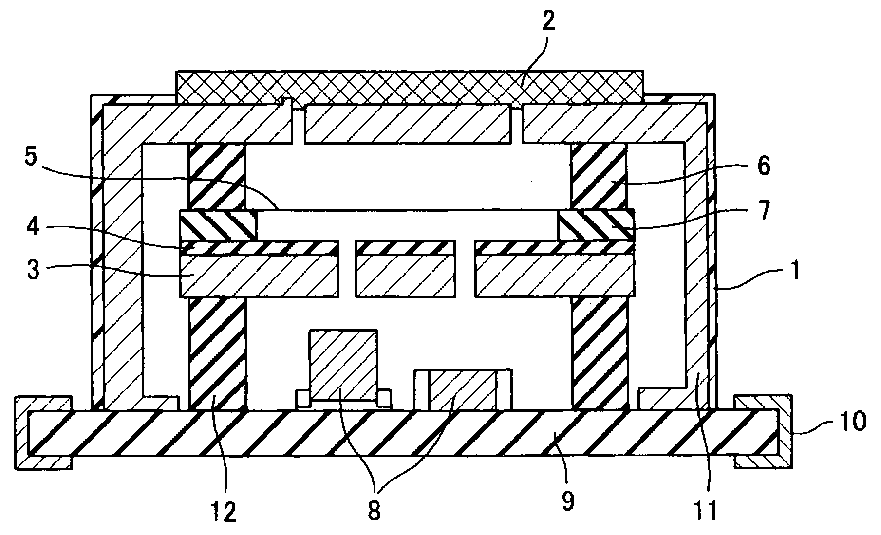
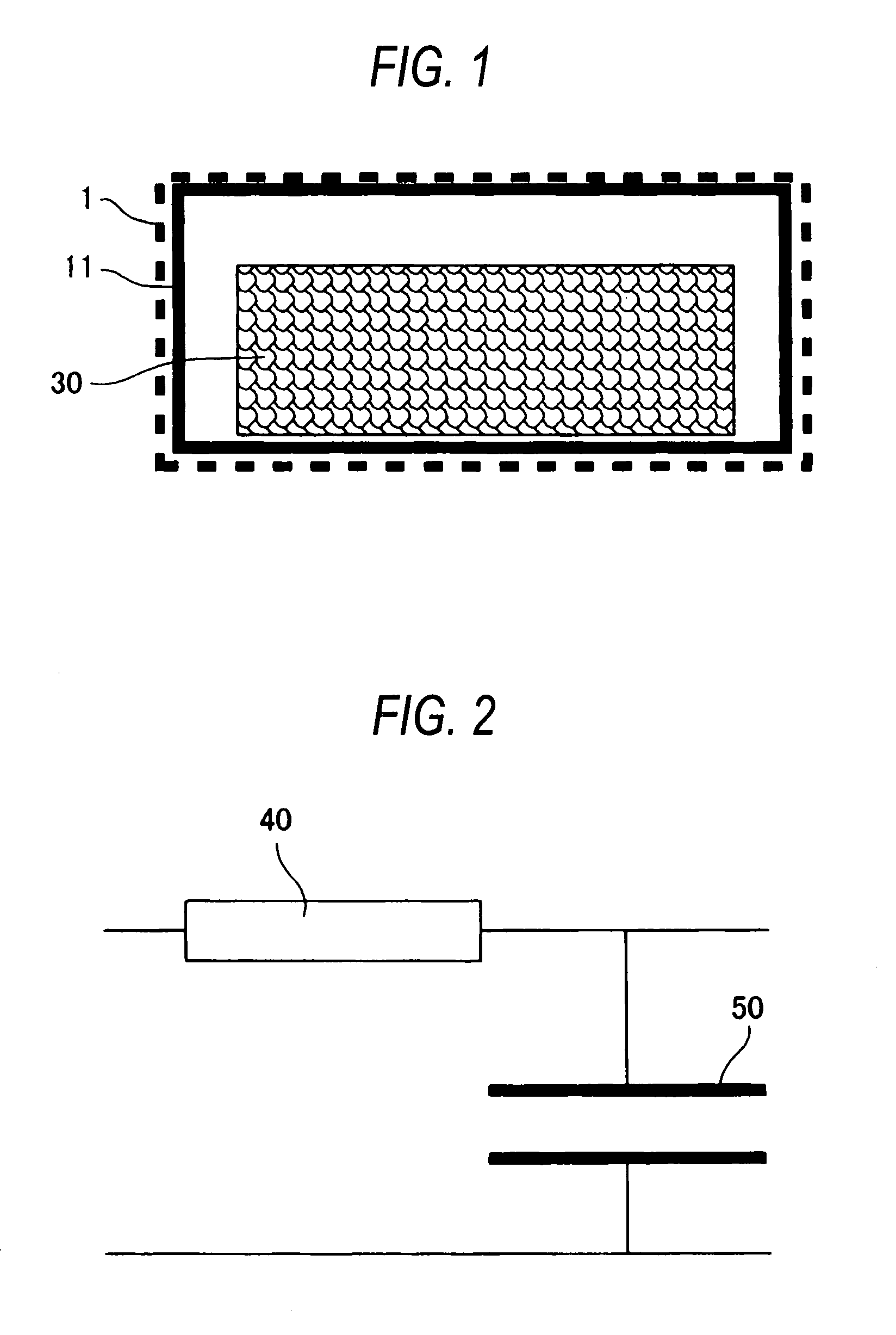
[0047]FIGS. 1 and 2 are diagrams showing the concept of the invention. FIG. 1 schematically shows the configuration, and FIG. 2 shows FIG. 1 in the form of an electric equivalent circuit diagram. As shown in FIG. 1, an electret condenser microphone of Embodiment 1 is characterized in that, on the outer surface of a microphone case 11, polyimide that is a nonmetallic material in which the deforming temperature is higher than the charge dissipating temperature of the dielectric layer that becomes the electret, the thermal resistance is high, and the thermal capacity is large is used as coating 1 of the case, whereby the microphone is protected so that, when the microphone is passed through a reflow solder bath, the interior of the case, particularly, the dielectric layer does not reach the charge dissipating temperature. A group of components in the case is indicated by 30. Referring to FIG. 2, a resistor indicates 40, and a capacitor indicates 50. The left side of the resistor 40 cor...

embodiment 2

[0061]A second embodiment of the invention will be described.

[0062]In Embodiment 1, the example in which PTFE is used as the electret film has been described. When a silicon oxide film (SiO2) is used in place of PTFE, it is possible to attain the same effects.

[0063]FIG. 5 is a view showing an electrode structure in which a silicon oxide film is used as an electret film. The case and other peripheral components are formed in the same manner as those of Embodiment 1. In the embodiment, the vibrating diaphragm comprises: a silicon substrate 13; a silicon oxide film 14 which functions as an electret; a silicon nitride film 15 which coats the periphery of the silicon oxide film; a metal film 16 which is formed on the rear face of the silicon substrate 13; and vacant holes 17 which are disposed in the silicon substrate 13.

[0064]Desirably, the silicon oxide film 14 is formed by the plasma CVD method or the low-pressure CVD method. The reason of this is that the temperature in film growth c...


PUM

PropertyMeasurementUnit
thicknessaaaaaaaaaa
surface potentialaaaaaaaaaa
temperatureaaaaaaaaaa

Abstract

The outer face of a case which accommodates a whole microphone is coated by a material having a heat conductivity which is lower than that of a metal, and a material transforming temperature which is higher than the charge dissipating temperature of a dielectric layer for forming an internal electret, and which is higher than 260° C., so that the internal temperature rise can be mitigated by the thermal resistance and the thermal capacity of the whole interior. When a microphone is attached to an application equipment, particularly, the microphone may be passed through a reflow solder bath for a short time period. A heat-resistant structure which can prevent the function from being impaired by a high temperature in the period is provided.

Description

RELATED APPLICATIONS[0001]This application is the U.S. National Phase under 35 U.S.C. § 371 of International Application No. PCT / JP2005 / 014333, filed on Aug. 4, 2005, which in turn claims the benefit of Japanese Application No. 2004-230407, filed on Aug. 6, 2004, the disclosures of which Applications are incorporated by reference herein.TECHNICAL FIELD[0002]The present invention relates to an electret condenser microphone which is mounted on an information communication equipment such as a cellular phone.BACKGROUND ART[0003]An electret condenser microphone was developed more than 30 years ago, and is still widely used as a component of a cellular phone and the like.[0004]FIG. 8 is a diagram showing the basic structure of an electret condenser microphone. Referring to FIG. 8, a protective cloth 101 is a cloth which is placed for the purpose of preventing dust or the like from entering, and which is configured by a cloth having a high sound transmission property, such as nonwoven clot...

Claims


Application Information

Patent Timeline
Patent Type & Authority Patents(United States)
IPC IPC(8): H04R25/00
CPCB81B7/0012H04R19/016B81B2201/0257H04R19/005H04R2499/11
Inventor MAKIHATA, KATSUHIROOGURA, HIROSHIYASUNO, YOSHINOBU
Owner PANASONIC CORP
Why Eureka
Try Eureka