Low-noise amplifier

a low-noise amplifier and amplifier technology, applied in the field of amplifiers, can solve the problems of high cost, inability to integrate with digital circuits, and low production cost of rf wireless integrated circuits using specific fabrication processes, so as to improve system power consumption and noise factor, and improve system gain

Inactive Publication Date: 2009-11-03
NAT TAIWAN UNIV
View PDF6 Cites 46 Cited by
  • Summary
  • Abstract
  • Description
  • Claims
  • Application Information

AI Technical Summary

Benefits of technology

[0012]In view of the disadvantages of the prior arts mentioned above, it is the primary objective of the present invention to provide a low-noise amplifier that has low power consumption and low production cost.
[0021]In view of the above, the low-noise amplifier of the present invention enhances the system gain via cascading three stages of amplifiers and decreases the system power consumption and noise factor via conjugate matching of impedance between the input matching network and the first amplifier stage, between the first and the second amplifier stages, between the second and the third amplifier stages, as well as between the third amplifier stage and the output matching network.

Problems solved by technology

Therefore, how to design low-noise amplifiers has become an urgent issue.
Wireless communication technology has been rapidly developed, and the production cost of radio frequency (RF) wireless integrated circuit is becoming lower.
General prior RF integrated circuits using specific fabrication processes, such as GaAs HEMT and SiGe HBT, not only have high cost, but also are unable to integrate with digital circuits, making system on chip (SOC) infeasible.
Also, the SOI process has higher production cost due to an isolation layer to separate active components from substrate in order to reduce power consumption.
However, this kind of bias will lower the linearity of amplifier.
The architecture of this low-noise amplifier consists of two common-source amplifiers, and low-pass filter circuits are used, hence this low-noise amplifier has rather high power consumption.

Method used


Image

  • Low-noise amplifier
  • Low-noise amplifier
  • Low-noise amplifier

Examples


Embodiment Construction

[0028]The following illustrative embodiments are provided to illustrate the disclosure of the present invention, these and other advantages and effects can be apparently understood by those in the art after reading the disclosure of this specification. The present invention can also be performed or applied by other different embodiments. The details of the specification may be on the basis of different points and applications, and numerous modifications and variations can be devised without departing from the spirit of the present invention.

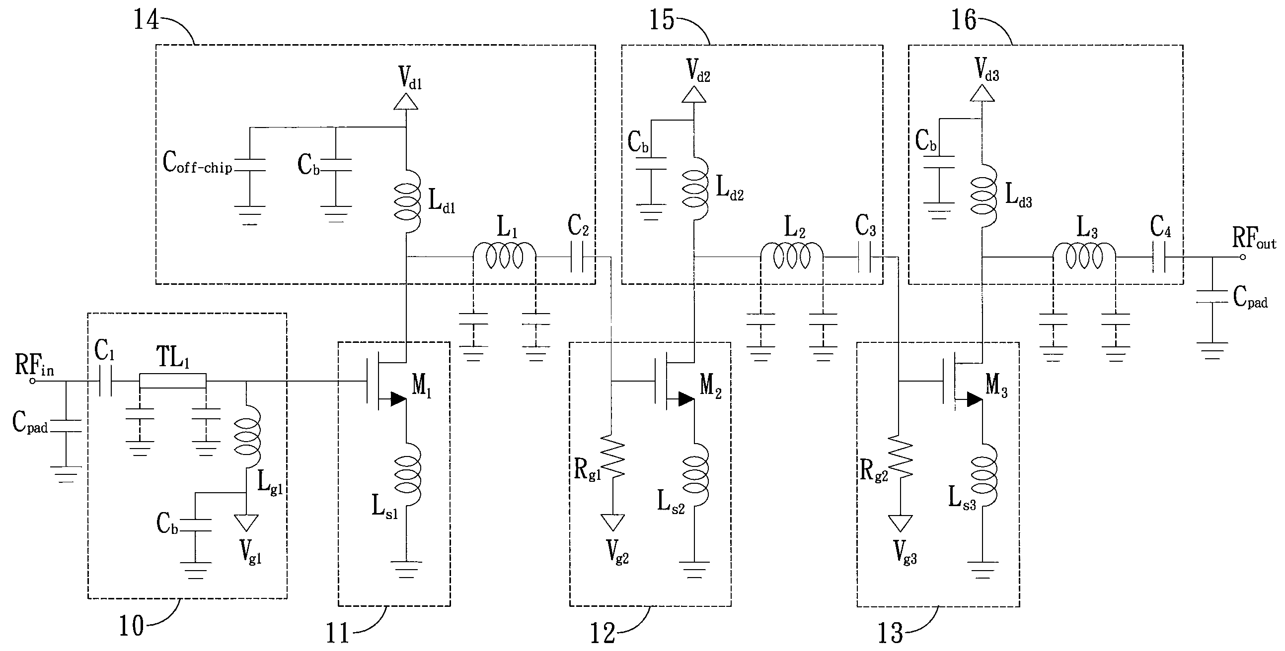
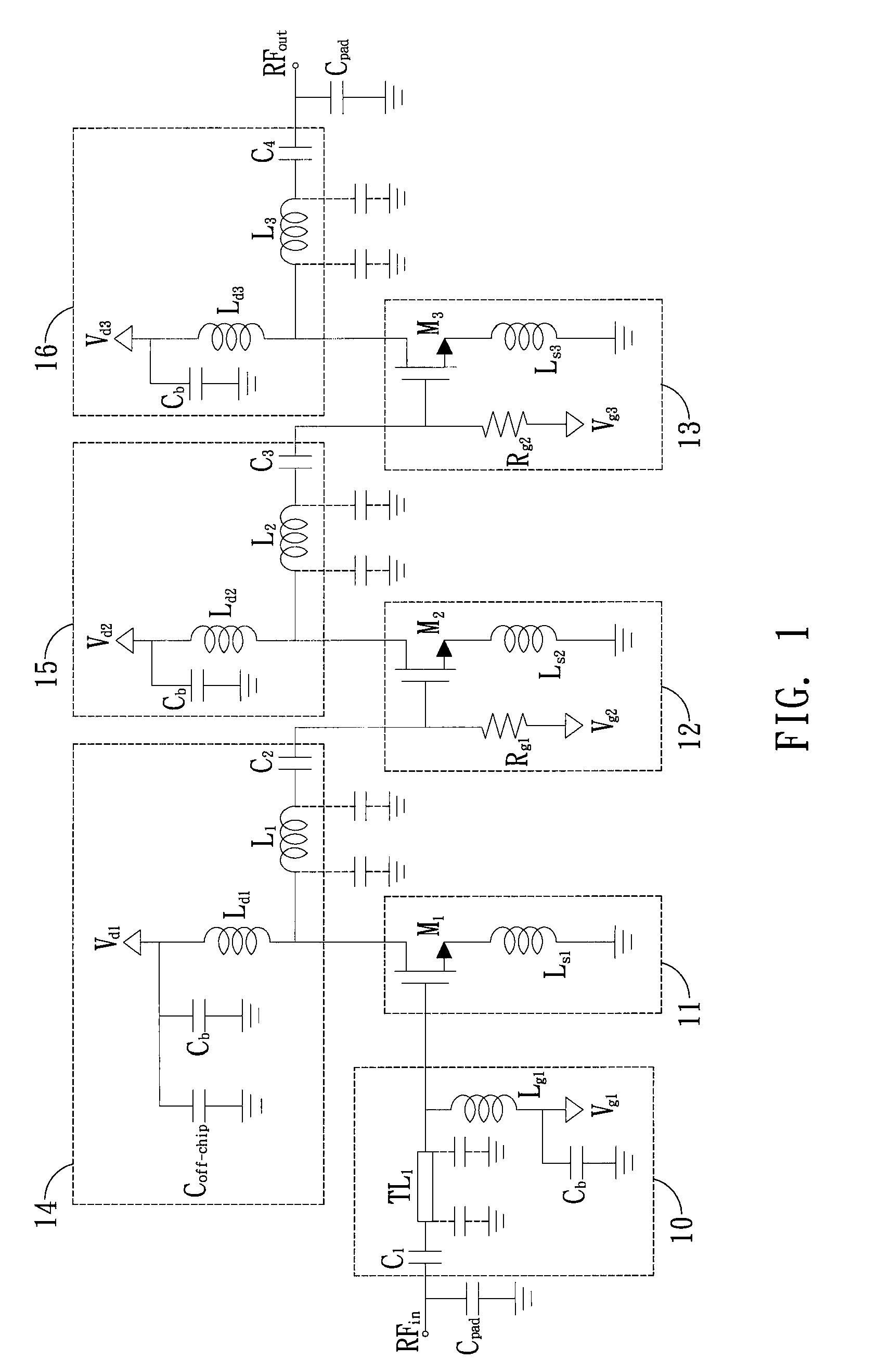
[0029]Please refer to FIG. 1, which is a circuit diagram of the low-noise amplifier of the present invention. The low-noise amplifier comprises an input matching network 10, a first amplifier stage 11, a second amplifier stage 12, a third amplifier stage 13, inter-stage matching networks 14 and 15, and an output matching network 16. Followed are detailed descriptions of the low-noise amplifier of the present invention.

[0030]When a radio-frequency...


PUM


Abstract

A low-noise amplifier is provided according to the present invention. The low-noise amplifier includes a first amplifier stage, a second amplifier stage, a third amplifier stage, an input matching network, inter-stage matching networks, and an output matching network. The impedance of the input matching network and the input impedance of the first amplifier stage are conjugate matched, thereby decreasing system power consumption and noise factor. The system gain is enhanced by cascading three stages of amplifiers.

Description

BACKGROUND OF THE INVENTION[0001]1. Field of the Invention[0002]This invention generally relates to amplifiers, and more specifically, to a low-voltage, low-power, and low-noise amplifier.[0003]2. Description of Related Art[0004]As consumers are getting more concerned about vehicle driving safety, in addition to antilock brake system (ABS) and air bags of vehicles, a vehicle anti-crash safety system would further enhance driving safety. Millimeter wave radar system is becoming an important technology of vehicle anti-crash safety system, and short-range radar sensor employed in the millimeter wave radar system consists of a transmitter and a receiver. A low-noise amplifier (LNA) is a part of the receiver of the short-range radar sensor. The low-noise amplifier, as a part of the receiver, amplifies received signals and suppresses noises caused by the receiver itself. Therefore, how to design low-noise amplifiers has become an urgent issue.[0005]Wireless communication technology has be...

Claims


Application Information

Patent Timeline
Patent Type & Authority Patents(United States)
IPC IPC(8): H03F3/04
CPCH03F1/0205H03F1/565H03F3/193H03F2200/108H03F2200/222H03F2200/492H03F2200/294H03F2200/318H03F2200/387H03F2200/408H03F2200/451H03F2200/255
Inventor DENG, PING-YUANKIANG, JEAN-FU
Owner NAT TAIWAN UNIV
Why Eureka
Try Eureka