Method and system for virtual prototyping

a virtual prototyping and prototyping technology, applied in the field of computer implemented electronic design automation techniques, can solve the problems of significant time delay, insufficient documentation alone, and code writing, and achieve the effect of reducing simulation overhead

Active Publication Date: 2009-11-03
SYNOPSYS INC
View PDF26 Cites 101 Cited by
  • Summary
  • Abstract
  • Description
  • Claims
  • Application Information

AI Technical Summary

Benefits of technology

[0021]An integrated design environment (IDE) is disclosed for simulating embedded systems. The IDE includes a graphical user interface and a design language for forming finite state machine models of hardware components that are coupled to processor simulators, preferably instruction set accurate simulators of processor cores. In one embodiment, the design language has graphical symbols adapted from the specification design language, is configured to reduce simulation overhead, and also includes features for modeling the signals of hardware elements. A virtual test bench may be coupled to the simulation to serve as a human-machine interface for interacting with the simulation. In one embodiment of virtual test bench, the virtual test bench includes a graphical representation of a user input interface and a graphical representation of an output display. A software debugger permits software to be loaded and executed for the simulation. In a preferred embodiment, the software debugger is adapted to permit at least one binary program code of a software application compiled for a target processor to be loaded by a user and executed on the virtual embedded system. One application of the IDE is to form a virtual embedded system having an execution speed sufficiently high to permit the evaluation of benchmark software executing on the virtual embedded system. In one embodiment, a virtual embedded system emulates the function of a physical evaluation board so that a virtual embedded system may be used to evaluate components of an embedded system, such as a processor core, in an evaluation phase of an embedded system project. Another application of the IDE is to form a virtual prototype of an embedded system having an execution speed sufficiently high to permit the virtual prototype to be used to develop software. In a preferred embodiment, a user may execute production quality embedded system code on the virtual prototype. In one embodiment, a virtual prototype is used during a development phase of an embedded system project to develop software. Still another application of the IDE is to form a virtual prototype that may be used as a design specification. In one embodiment, the virtual prototype is used as design specification to coordinate the actions of hardware and software developers during a development phase of an embedded system project. In another embodiment, the virtual prototype is used as a design specification for the procurement of a good or service related to the embedded system.

Problems solved by technology

However, typically a significant amount of code must be written for the software partition of a particular project.
Because of the nature of embedded system design, documentation alone is typically insufficient to understand how an IP component, such as a processor core, will function with a software application running user code.
In some cases, a significant time delay may be involved for a vendor to arrange for evaluation boards having custom silicon and printed circuit boards to be designed and manufactured.
Moreover, each evaluation board may have a significant cost (e.g., thousands of dollars) such that a vendor will only maintain in stock a limited number of evaluation boards at any one moment of time.
Consequently, in some cases embedded system designers may have to wait substantial periods of time to obtain an evaluation board.
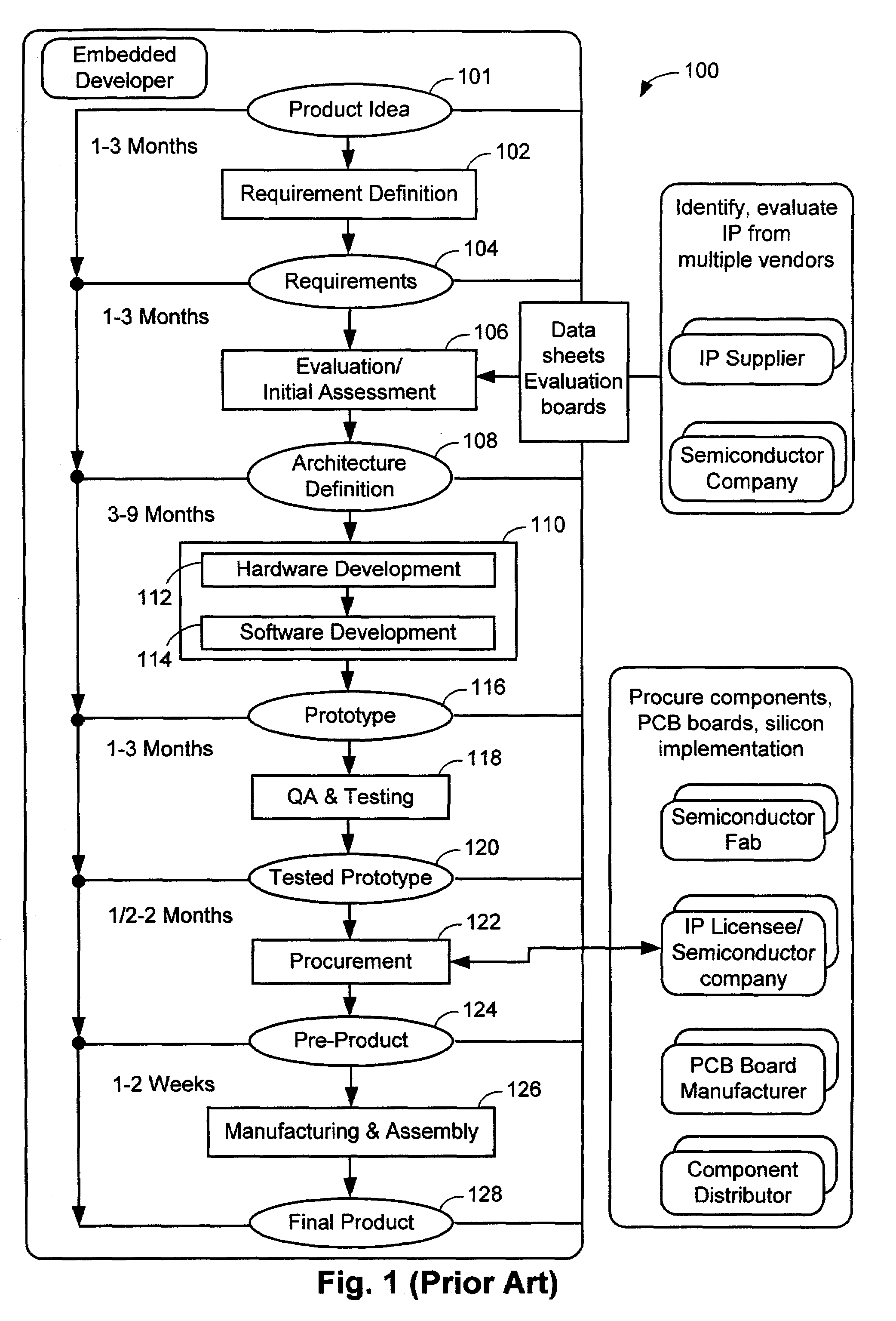
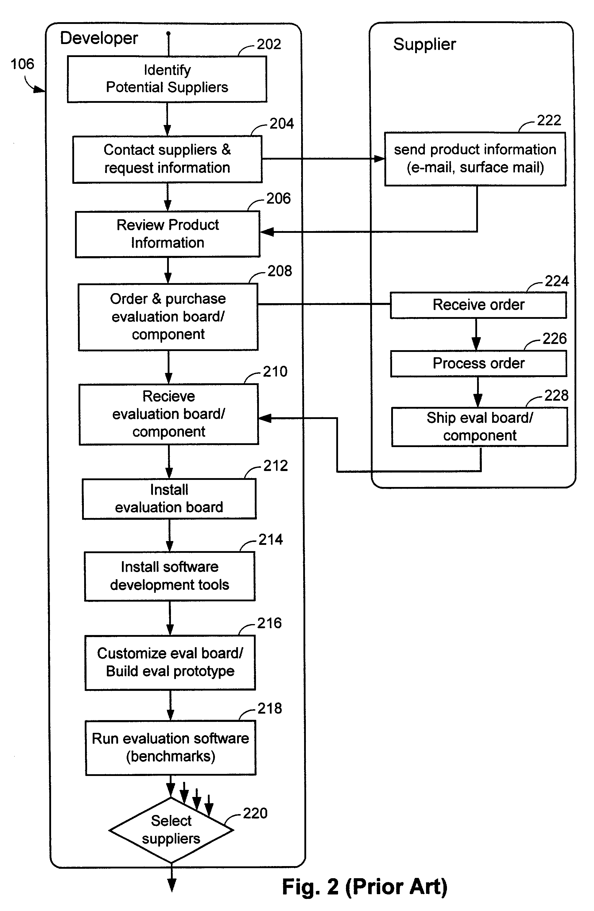
From the standpoint of the embedded system designer, the evaluation phase 106 is a time consuming and costly process, particularly if a significant number of IP blocks from different vendors are to be evaluated.
In addition to being a time consuming process, each IP block can be evaluated only in isolation, which can make it difficult to determine how several IP blocks would interact together in a single embedded system.
From the perspective of the IP vendor this is a costly marketing tool that requires IP vendors to invest in creating standard test board platforms (e.g., boards including reference peripheral devices and driver applications).
The cost to the IP vendor includes the cost of the evaluation boards and the support services that must be provided for potential customers to successfully evaluate each board.
Unfortunately it may take up to two-thirds of the development cycle before the hardware implementation reaches a high level of implementation detail and a physical hardware emulator 308 is configured.
However, a conventional hardware emulator is comparatively expensive.
In some embedded system projects a hardware emulator (e.g., a FPGA hardware emulator) may not be cost effective such that much of the software development and integration must wait until a physical prototype is available.
Procurement significantly earlier than the tested prototype stage 120 is typically impractical because there is an insufficient quantity and quality of documentation prior to the tested prototype stage that would permit procurement needs to be adequately communicated with vendors.
Embedded systems designers are under increasing pressure to reduce the time to market and to increase the software functionality of embedded systems, which in turn tends to increase the complexity of embedded system software.
However, conventional automated design tools have serious shortcomings that limit their usefulness in the design cycle, particularly for embedded systems executing complex software applications.
One drawback of conventional electronic design approaches for embedded systems is that they are hardware-centric and typically have an execution speed that is too slow for the simulation to serve as a hardware emulator for the purposes of debugging software.
However, modeling the hardware implementation in HDL requires that the hardware be extensively developed (e.g., fully detailed) before the software, which can require a significant length of time in the development cycle.
In addition to its other problems, a HDL simulation (e.g., one using a cycle-accurate processor model and a detailed implementation model of hardware) has such a high level of implementation detail that a software application executed on HDL simulation of the hardware partition would be too slow for meaningful software debugging during a typical development phase.
However, HDL models typically execute at too slow a speed to permit a software designer to evaluate the system aspects in which a software designer is interested.
A further drawback of HDL models is that it is often impractical to share them with third parties that are not legally bound to maintain the confidentiality of the model.
HDL models have such a high level of implementation detail that companies are reluctant to share HDL models with other companies for fear of losing valuable proprietary trade secrets.
As one consequence, IP vendors typically do not provide HDL models of their products for evaluation.
Another consequence is that embedded system designers and IP vendors typically do not make HDL models of IP components and sub-systems available on the Internet.
The problems associated with conventional embedded system design projects can be anticipated to become worse as improvements in the processing power of embedded systems permits embedded systems having more complex software applications.
However, conventional automated design tools do not provide the right level of abstraction, quick model creation, ease of use, execution speed, and understandability to permit substantial improvements in the evaluation, development, and procurement phases of an embedded system design project.

Method used


Image

  • Method and system for virtual prototyping
  • Method and system for virtual prototyping
  • Method and system for virtual prototyping

Examples


Embodiment Construction

[0083]The present invention generally includes a computer-implemented technique for simulating an embedded system using a graphical integrated development environment (IDE) design application that has features for rapidly creating and evaluating virtual embedded systems (also known as “virtual platforms” or “virtual prototypes” for new designs) and that has a sufficient simulation speed and test features to permit evaluation, development, and debugging of an embedded system software application to be performed with a virtual embedded system.

[0084]FIG. 4A is a block diagram illustrating major software modules of a preferred embodiment of the IDE 402. Further details on the interfaces coupling the software modules are described below in more detail. The software modules of IDE 402 may reside on a memory 450 of a computer 460 having a computer processor and memory, such as personal computer or computer coupled to a network server. It will also be understood that the IDE 402 may be stor...


PUM


Abstract

An integrated design environment (IDE) is disclosed for forming virtual embedded systems. The IDE includes a design language for forming finite state machine models of hardware components that are coupled to simulators of processor cores, preferably instruction set accurate simulators. A software debugger interface permits a software application to be loaded and executed on the virtual embedded system. A virtual test bench may be coupled to the simulation to serve as a human-machine interface. In one embodiment, the IDE is provided as a web-based service for the evaluation, development and procurement phases of an embedded system project. IP components, such as processor cores, may be evaluated using a virtual embedded system. In one embodiment, a virtual embedded system is used as an executable specification for the procurement of a good or service related to an embedded system.

Description

[0001]This application claims priority from U.S. Provisional Application No. 60 / 208,900, entitled “Method and System For Online Virtual Prototyping,” filed Jun. 2, 2000, and U.S. Provisional Application No. 60 / 230,171, entitled “Method and System For Online Virtual Prototyping With Walkthrough Function,” filed Sep. 1, 2000. The entire contents of U.S. Provisional Application Nos. 60 / 230,171 and 60 / 208,900 are hereby incorporated by reference in their entirety.BACKGROUND OF THE INVENTION[0002]1. Field of the Invention[0003]The present invention relates generally to computer implemented electronic design automation techniques to evaluate, design, and simulate embedded systems. More particularly, the present invention is directed towards the use of computer implemented techniques for the evaluation of Intellectual Property components used in embedded systems, the design of embedded systems, and the procurement of goods and services related to an embedded system.[0004]2. Description of ...

Claims


Application Information

Patent Timeline
Patent Type & Authority Patents(United States)
IPC IPC(8): G06F17/50
CPCG06F17/5022G06F17/5045G06F2217/66G06F2217/04G06F2111/02G06F2115/08G06F30/30G06F30/33G06F30/3308
Inventor BADE, STEPHEN LBEN-CHORIN, SHAYCAAMANO, PAULMONTOREANO, MARCELO ETAGGU, ANITHEON, FILIP CWILLS, DEAN C
Owner SYNOPSYS INC
Why Eureka
Try Eureka