
System for magnetic scanning and correction of an ion beam

a scanning and ion beam technology, applied in the field of ion beam scanning and correction systems, can solve the problems of space-charge blowup, unmanageable beam envelope, and limit the amount of beam current that can be delivered to a target workpiece, so as to facilitate ion implantation, reduce the effect of space-charge blowup, and mitigate the effect of zero field

Active Publication Date: 2009-11-10
AXCELIS TECHNOLOGIES
View PDF14 Cites 19 Cited by
  • Summary
  • Abstract
  • Description
  • Claims
  • Application Information

AI Technical Summary

Benefits of technology

The invention is about a device called a magnetic scanner that is used to control the movement of ions during a process called ion implantation. The device uses constant magnetic fields to prevent distortion in the magnetic field during periods of low magnetic field amplitude. This results in a smoother and more accurate movement of the ions, which can improve the quality of the implantation process. The invention can be applied to various scanners and systems for ion implantation.

Problems solved by technology

One drawback to an electric scanner is that it can cause space-charge blowup and thereby limit the amount of beam current that can be delivered to a target workpiece.
Nonzero fields of the electric scanner remove the electrons from self-neutralization and cause the beam within the scanner to blow up, which can result in a beam envelope unmanageably large and thus beam current loss.
However, it has been noted that the ion beam goes through an anomalous transport phase when the magnetic field in the scanning magnet has zero or close to zero amplitude.
However, this technique adds complexity to the scanner assembly in terms of adding a secondary magnetic circuit.
Additionally, it immerses the complete scanner volume in a minimum field whose effects on beam transport, i.e. steering and focusing of an additional magnetic field, have to be taken into account, which increases the complexity of the beamline design.

Method used


Image

  • System for magnetic scanning and correction of an ion beam
  • System for magnetic scanning and correction of an ion beam
  • System for magnetic scanning and correction of an ion beam

Examples


Embodiment Construction

[0022]The present invention will now be described with reference to the drawings wherein like reference numerals are used to refer to like elements throughout, and wherein the illustrated structures are not necessarily drawn to scale.

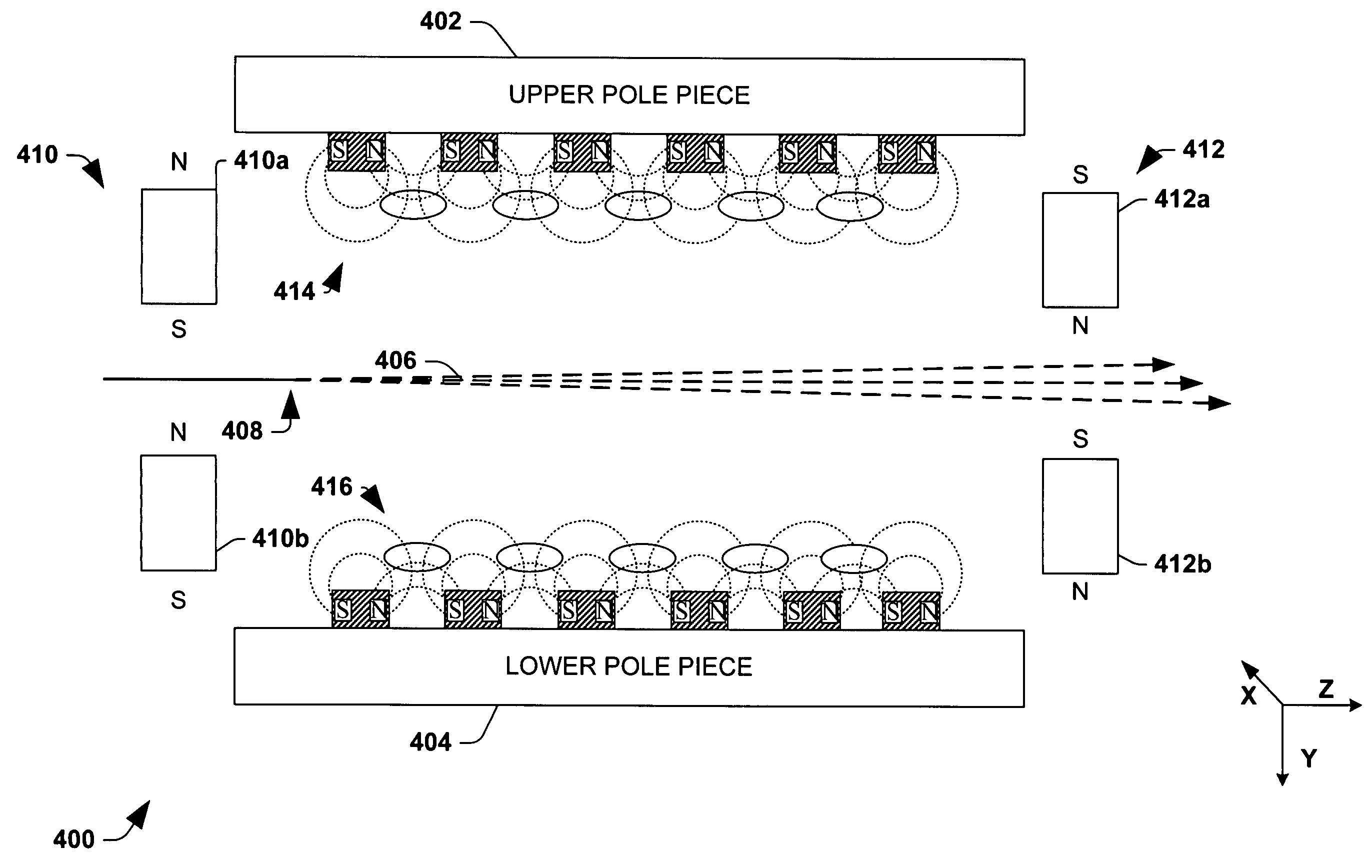
[0023]Aspects of the present invention facilitate ion implantation by mitigating the zero field effect, which typically occurs in magnetic based scanners during time periods of zero or about zero magnetic field amplitudes. A constant magnetic field is applied to an ion beam near or within the magnetic scanner in order to mitigate the zero field effect and smooth the flux profile.

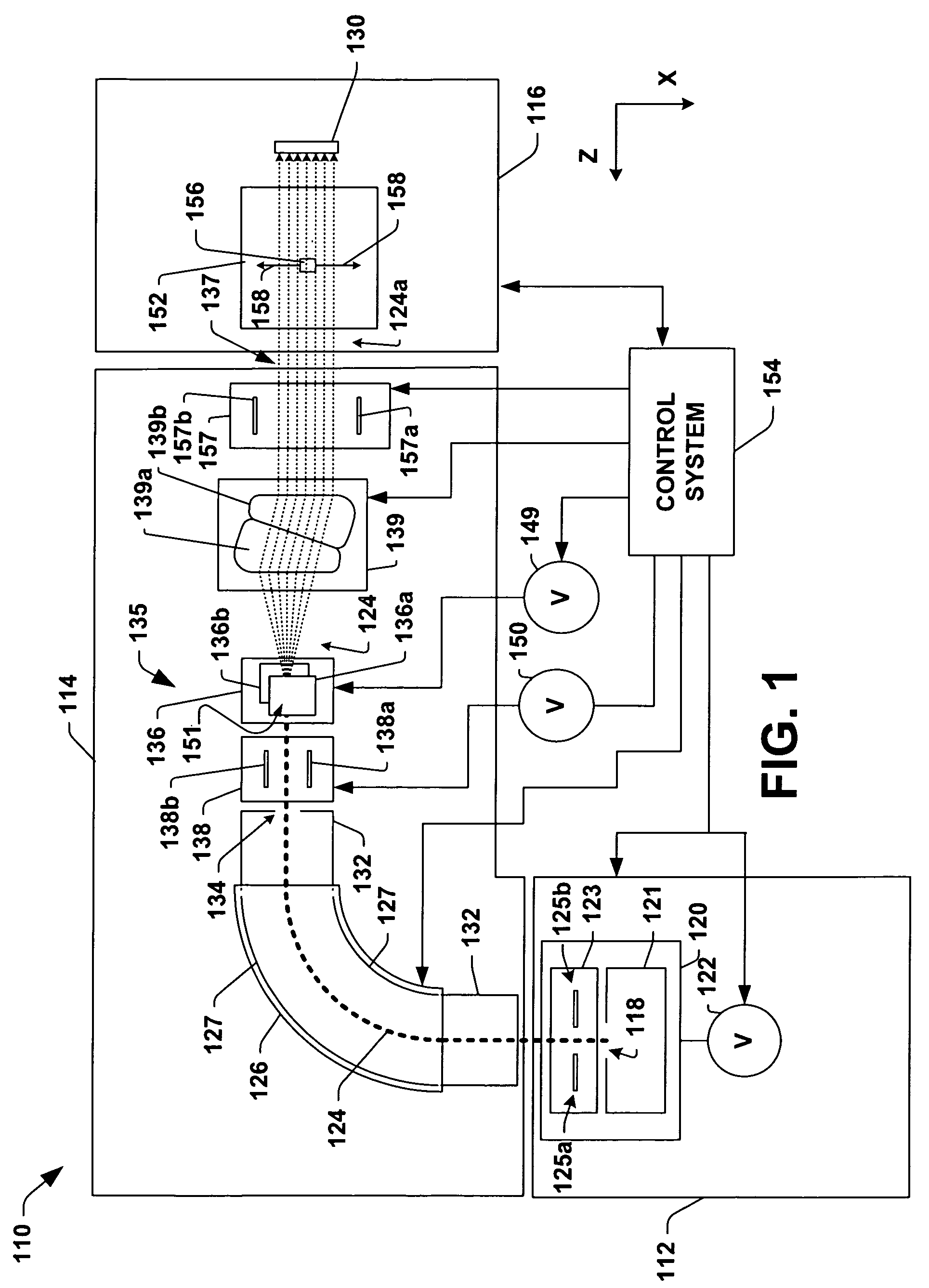
[0024]FIG. 1 illustrates an example ion implantation system 110 in accordance with an aspect of the present invention. The system 110 is presented for illustrative purposes and it is appreciated that aspects of the invention are not limited to the described ion implantation system and that other suitable ion implantation systems can also be employed.

[0025]The system 110 has a te...


PUM


Abstract

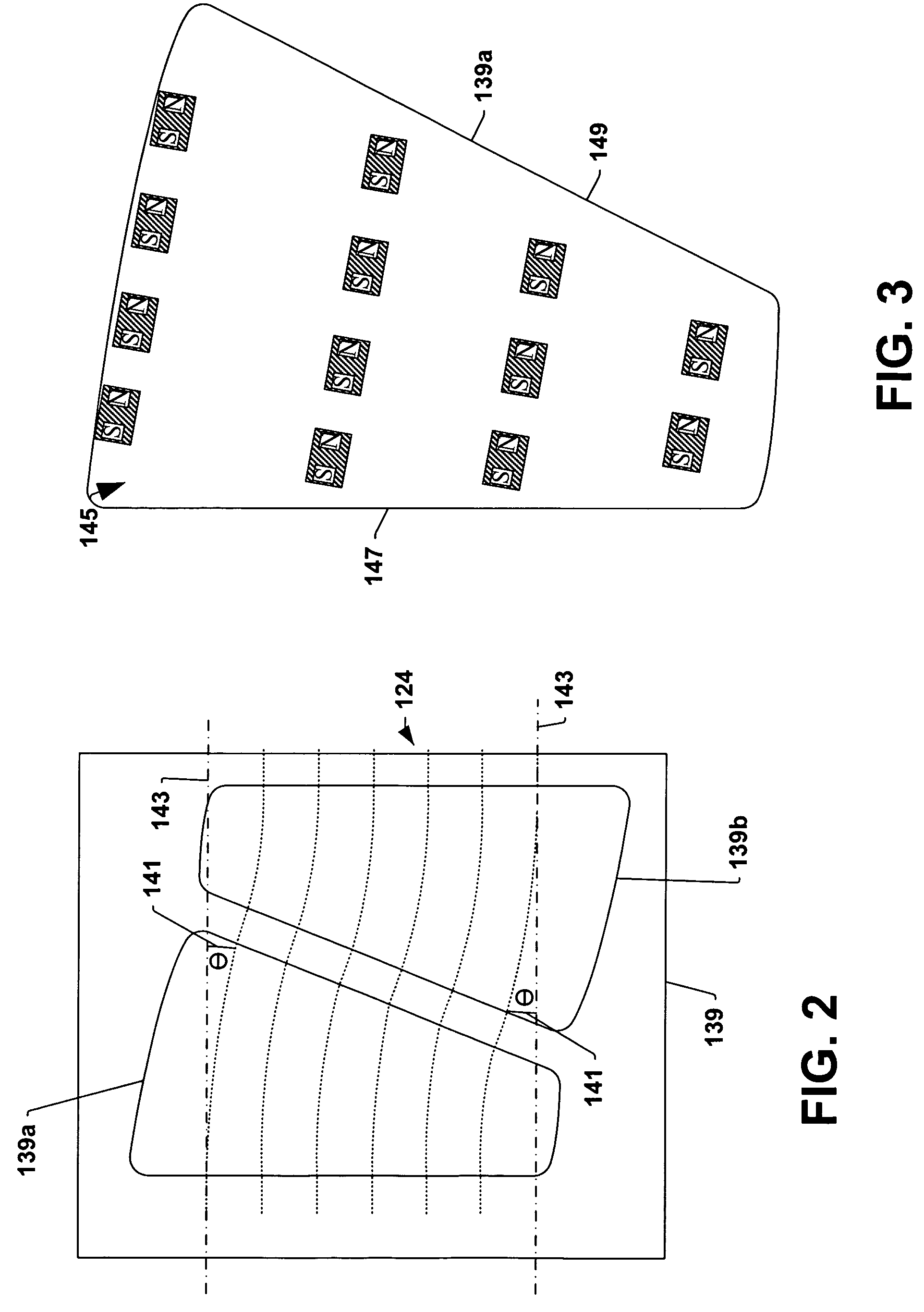
A magnetic scanner employs constant magnetic fields to mitigate zero field effects. The scanner includes an upper pole piece and a lower pole piece that generate an oscillatory time varying magnetic field across a path of an ion beam and deflect the ion beam in a scan direction. A set of entrance magnets are positioned about an entrance of the scanner and generate a constant entrance magnetic field across the path of the ion beam. A set of exit magnets are positioned about an exit of the scanner and generate a constant exit magnetic field across the path of the ion beam.

Description

FIELD OF THE INVENTION[0001]The present invention relates generally to ion implantation systems, and more specifically to systems and methods for scanning and correcting ion beams.BACKGROUND OF THE INVENTION[0002]In the manufacture of semiconductor devices, ion implantation is used to dope semiconductors with impurities or dopants. Ion implanters are used to treat silicon wafers with an ion beam, in order to produce n or p type extrinsic material doping or to form passivation layers during fabrication of an integrated circuit. When used for doping semiconductors, the ion implanter injects a selected ion species to produce the desired extrinsic material. Implanting ions generated from source materials such as antimony, arsenic or phosphorus results in “n type” extrinsic material wafers, whereas if “p type” extrinsic material wafers are desired, ions generated with source materials such as boron, gallium or indium may be implanted.[0003]Typical ion implanters include an ion source for...

Claims


Application Information

Patent Timeline
Patent Type & Authority Patents(United States)
IPC IPC(8): H01J37/317
CPCH01J37/026H01J37/1475H01J37/3171H01J2237/055H01J2237/004H01J2237/0041H01J37/317H01L21/265
Inventor VANDERBERG, BO H.RATHMELL, ROBERT D.EISNER, EDWARD C.
Owner AXCELIS TECHNOLOGIES
Learn More