Method and system for increasing the isolation characteristic of a crossed dipole pair dual polarized antenna

a dual-polarized antenna and isolation characteristic technology, applied in the direction of polarised antenna unit combinations, antenna details, antennas, etc., can solve the problems of undesirable leakage signal at one of these ports, difficult to achieve physical separation between antenna arrays and/or antenna elements, and often inapplicability, so as to improve the isolation characteristic of rf signals and increase the isolation characteristic of crossed dipole pairs

Active Publication Date: 2009-11-10
COMMSCOPE TECH LLC
View PDF32 Cites 21 Cited by
  • Summary
  • Abstract
  • Description
  • Claims
  • Application Information

AI Technical Summary

Benefits of technology

[0027]A method and system for increasing an isolation characteristic of a crossed dipole pair, dual polarized antenna can include a feedback system comprising a feedback element for generating a feedback signal in response to a transmitted RF signal produced by each radiating elements of a crossed dipole pair, dual polarized antenna. In such an exemplary embodiment, the feedback element may improve the isolation characteristic of RF signals between two different polarizations.
[0036]According to another further exemplary aspect, the fastening mechanism can include spring feet that are milled out of the feedback element itself. These spring feet can then snap the feedback element into place on the center of the crossed dipole pair, dual polarized antenna. The spring feet can contact the center portion of the crossed dipole pair, dual polarized antenna. The use of adhesive may be eliminated in this exemplary embodiment.
[0038]Each feedback element can be made of a metal, such as stainless steel or aluminum. The metal of the feedback element can be readily combined with one of the fastening mechanisms described above. Such feedback elements are conducive for high volume production environments while maintaining high quality standards. The manufacturing processes for such feedback elements can provide the advantage of small tolerances.
[0040]The feedback signal that can be produced by each feedback element can be received by each radiator or dipole of the crossed dipole pair dual polarized antenna. Each radiator or dipole can also be described as a radiating element, and may radiate any leakage signal present at the output port of the antenna. Because the feedback signal and the leakage signal are set to the same frequency and are usually approximately 180 degrees out of phase, this signal summing operation serves to cancel both signals at the output port, thereby improving the port-to-port isolation characteristic of the antenna.
[0042]In an alternate exemplary embodiment, the feedback elements can be combined with multiple frequency band radiating crossed dipole pair dual polarized antenna elements. In this way, signals between different operating frequencies can be isolated from one another.

Problems solved by technology

While this physical separation between like antenna arrays 100 can reduce electrical interference and increase electrical isolation, this arrangement is often not practical given the tight spacing and electronic packaging requirements imposed on most antennas.
That is, physical separation between antenna arrays and / or antenna elements is often not possible when antennas are required to occupy a space or volume that may be smaller than the optimal antenna wavelength separation.
An undesirable leakage signal can appear at one of these ports as a result of a signal present at the opposite port and part of that signal being electrically coupled, undesirably so, to the opposing port.
Poor receive sensitivity, and poor radiated output, often results due to internal antenna loss when part of one of the signals at one input port (port one) leaks or is otherwise coupled as a leakage signal to the other port (port two).
Such leakage or undesired coupling of a signal from one port to the other may adversely combine with the signal at the other port to diminish the strength of both signals and hence reduce the effectiveness of the antenna.
When port-to-port isolation is minimal, i.e., leakage is maximum, the antenna system will perform poorly in the receive mode in that the reception of incoming signals will be limited only to the strongest incoming signals and lack the sensitivity to pick up faint signals due to the presence of leakage signals interfering with the weaker desired signals.
In the transmit mode, the antenna performs poorly due to leakage signals detracting from the strength of the radiated signals.
A dual band, crossed dipole dual polarized antenna array 117 can further complicate the isolation problem because there can be interference between the two orthogonal radiated fields in a single frequency band, as well as interference between the high frequency and low frequency band antenna elements 115A, 115B.
Impedance mismatching can cause leakage signals to occur and degrade the port-to-port isolation if (1) a cross-coupling mechanism is present within the distribution network or in the radiating elements, or if (2) reflecting features are present beyond the radiating elements.
In a dual polarized antenna system, the reflected signal can result in a leakage signal at the opposite port or the same port and it can cause a significant degradation in the overall isolation characteristic and performance of the antenna system.
While impedance matching helps to increase port-to-port isolation, it falls short of achieving the high degree of isolation that is now required in the wireless communications industry.
However, as noted above, the physical area and dimensional constraints placed on the antenna designs of today for use in cellular base station towers generally render the physical separation technique impractical in all but a few instances.
These techniques can help in increments, but usually do not solve the magnitude of the signal leakage problem.
While the conductors, according to this technique, can increase the isolation characteristic, the foam bars that support the conductive strips positioned between crossed dipole pair antennas can have mechanical properties that are not conducive to the operating environment of the antenna.
Such materials are usually bulky and are difficult to accurately and precisely position between antenna elements.
Additionally, these support blocks have coefficients of thermal expansion that are typically not conducive to extreme temperature fluctuations in the outside environment in which the antenna functions, and they readily expand and contract depending on temperature and humidity.
In addition to the problems with thermal expansion, the support blocks are also not conducive for rapid and precise manufacturing.
Furthermore, these types of support blocks do not provide for accurate placement of the conductive strips or feedback elements on the distribution network board.

Method used


Image

  • Method and system for increasing the isolation characteristic of a crossed dipole pair dual polarized antenna
  • Method and system for increasing the isolation characteristic of a crossed dipole pair dual polarized antenna
  • Method and system for increasing the isolation characteristic of a crossed dipole pair dual polarized antenna

Examples


Embodiment Construction

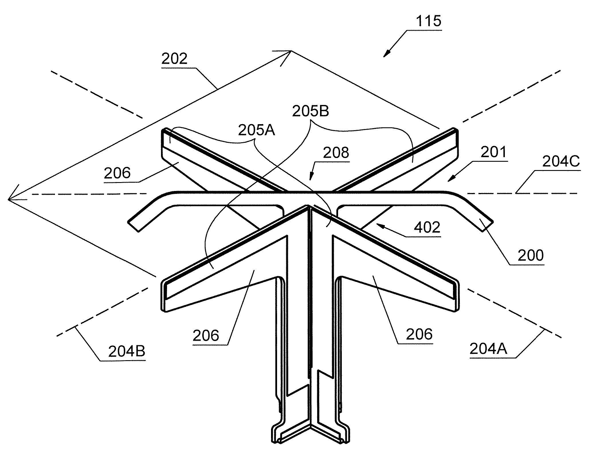
[0071]A method and system for increasing an isolation characteristic of a crossed dipole pair, dual polarized antenna can include a feedback system comprising a feedback element for generating a feedback signal in response to a transmitted RF signal produced by each radiating elements of a crossed dipole pair, dual polarized antenna. In such an exemplary embodiment, the feedback element may improve the isolation characteristic of RF signals between two different polarizations.

[0072]One inventive aspect of the technology can include positioning of the feedback element relative to the radiators of the crossed dipole pair antenna. The feedback element can “float” above the crossed dipole pair radiator at a distance of approximately 0.007 of a wavelength at an operating frequency of the crossed dipole pair, dual polarized antenna. The length of the feedback element can be between approximately one-eighth and one-half of a wavelength of the operating frequency of the crossed dipole pair ...


PUM


Abstract

A method and system for increasing an isolation characteristic of a crossed dipole pair, dual polarized antenna can include a feedback system comprising a feedback element for generating a feedback signal in response to a transmitted RF signal produced by each radiating elements of a crossed dipole pair, dual polarized antenna. The feedback element may improve the isolation characteristic of RF signals between two different polarizations. The dimensions and spacing of the feedback element relative to an antenna may provide for optimal feedback signals. The feedback element can have a length, width, and thickness wherein the length and width are usually larger than the thickness dimension. A fastening mechanism of the inventive feedback system for coupling the feedback element to the antenna can include materials that allow for high speed production of antenna arrays using with the feedback system.

Description

STATEMENT REGARDING RELATED APPLICATIONS[0001]The present application claims priority to provisional application entitled, “Isolation Card for Antennas,” filed on Aug. 26, 2005 and assigned U.S. Application Ser. No. 60 / 711,959. The entire contents of the provisional patent application are hereby incorporated by reference.FIELD OF INVENTION[0002]This invention relates to antennas for communicating electromagnetic signals and, more particularly, to improving sensitivity of a crossed dipole pair dual polarized antenna by increasing the isolation characteristic of the antenna.BACKGROUND OF THE INVENTION[0003]Many types of antennas are in wide use today throughout the communications industry. The antenna has become an especially critical component for an effective wireless communication system due to recent technology advancements in areas such as Personal Communications Services (PCS), cellular mobile radiotelephone (CMR) service, and Advanced Mobile Phone System (AMPS) service.[0004]So...

Claims


Application Information

Patent Timeline
Patent Type & Authority Patents(United States)
IPC IPC(8): H01Q21/26
CPCH01Q1/246H01Q21/26H01Q1/523
Inventor TILLERY, JAMES K.
Owner COMMSCOPE TECH LLC
Why Eureka
Try Eureka