Gas diffusion electrode and method of making the same

a technology of gas diffusion electrodes and electrodes, which is applied in the direction of cell components, final product manufacturing, sustainable manufacturing/processing, etc., can solve the problem of electrical shorting of the electrochemical devi

Active Publication Date: 2009-12-08
PLUG POWER
View PDF16 Cites 6 Cited by
  • Summary
  • Abstract
  • Description
  • Claims
  • Application Information

AI Technical Summary

Benefits of technology

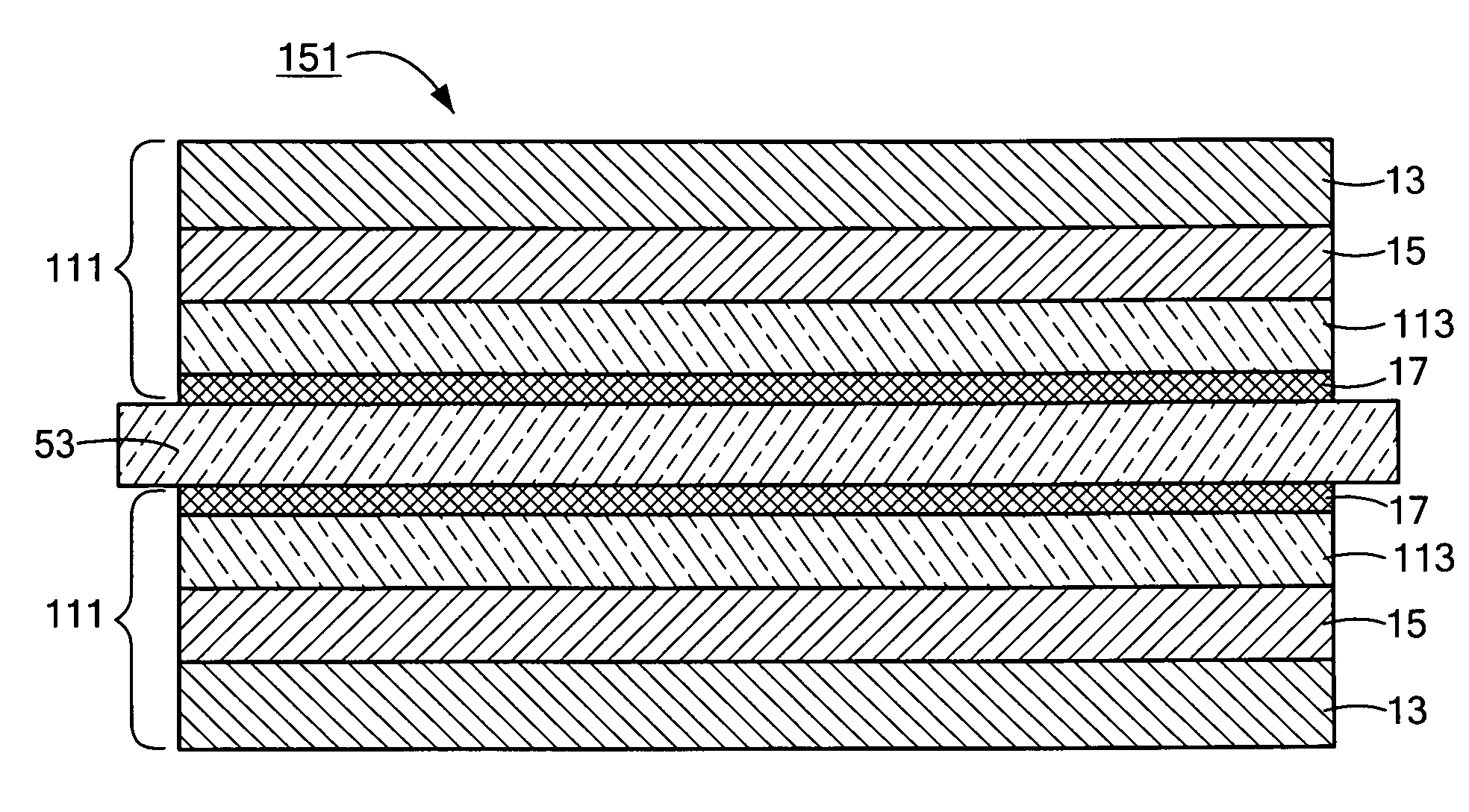
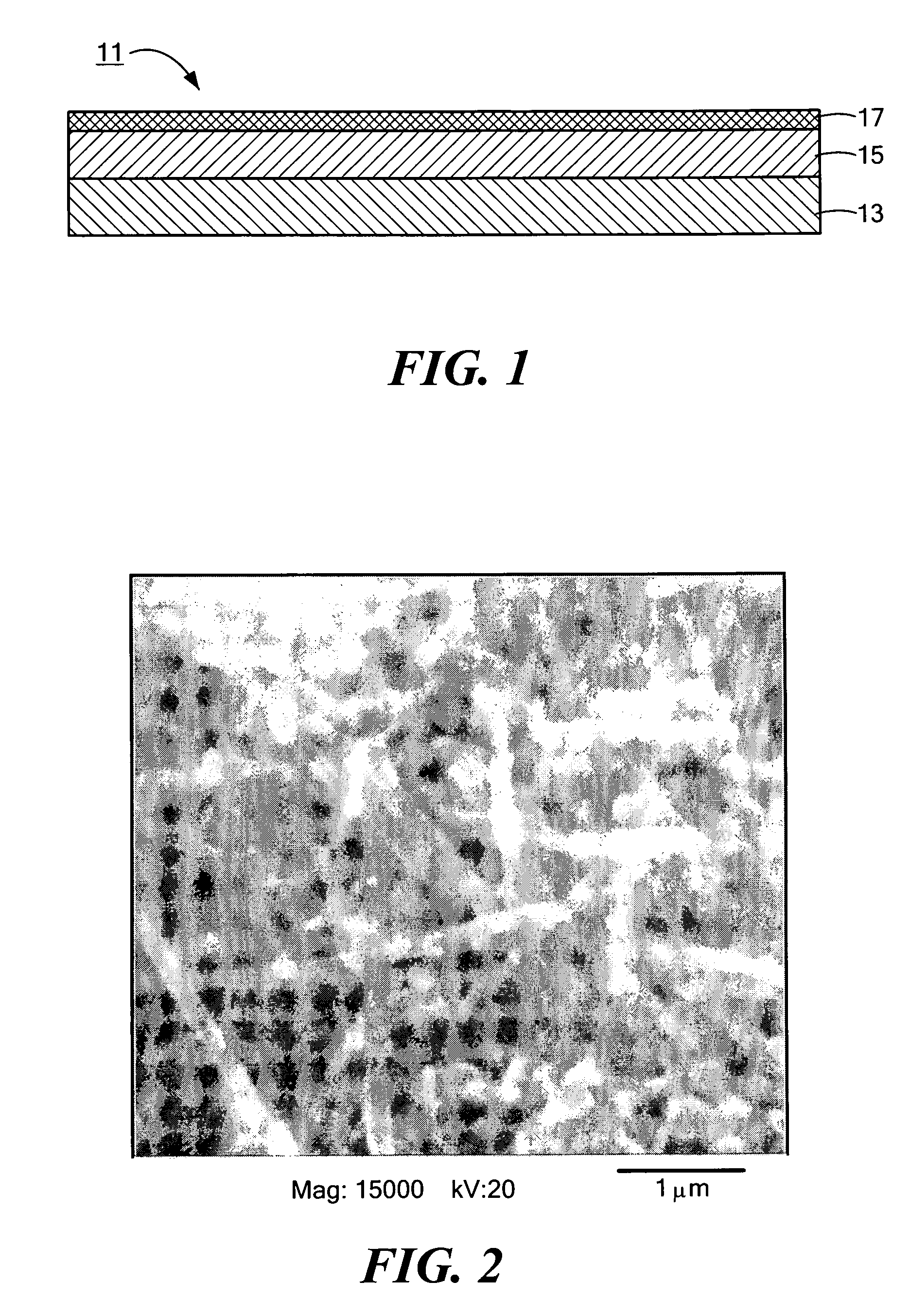
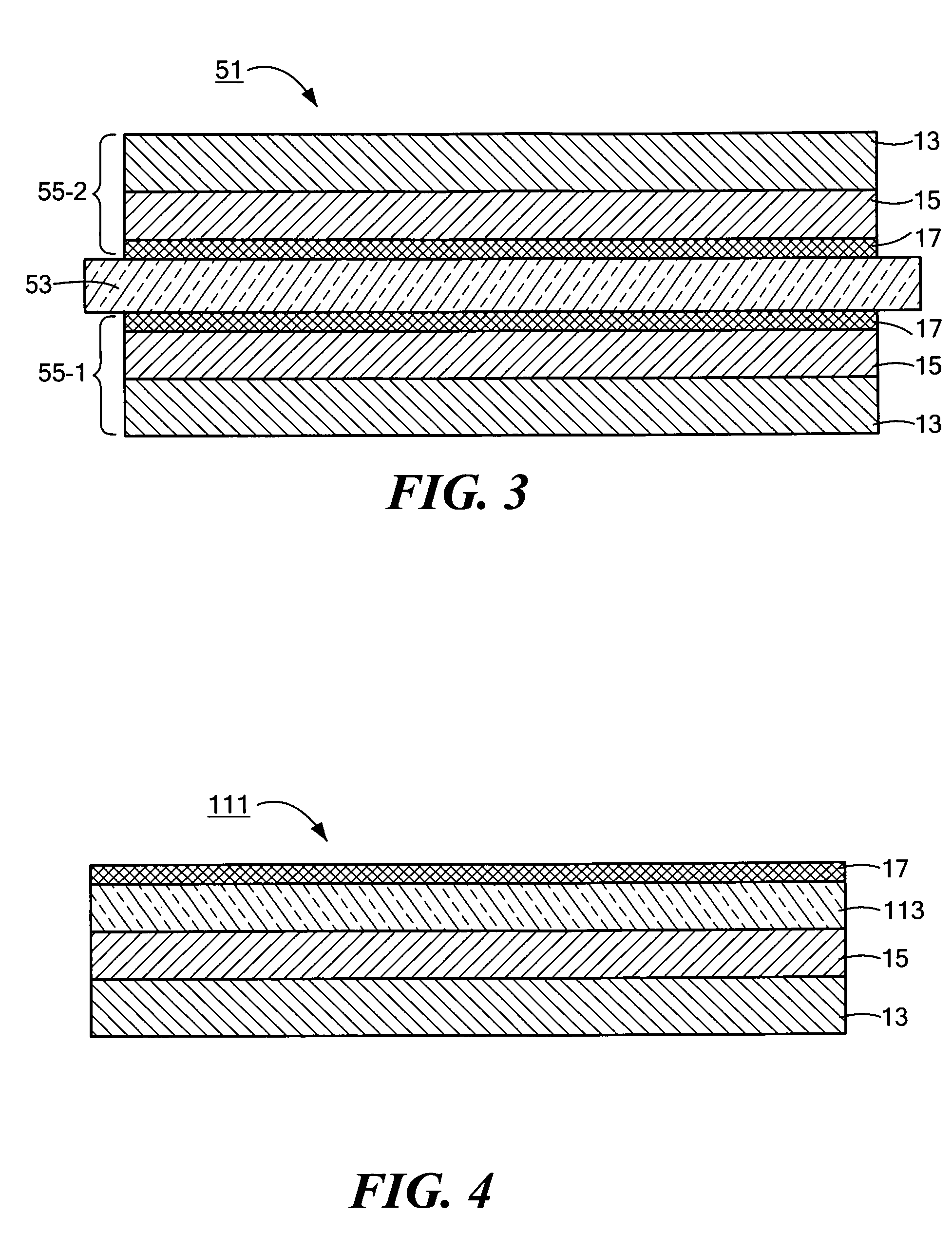
[0014]In a second preferred embodiment, the gas diffusion electrode further comprises a second cushioning layer, the second cushioning layer being an electrically-conductive porous structure in direct contact with the exposed surface of the first cushioning layer. The second cushioning layer is similar to the first cushioning layer, except that the carbon nanofibers of the first cushioning layer are replaced with carbon black or a combination of carbon nanofibers and carbon black in the second cushioning layer. The use of carbon black in the second cushioning layer permits one to adjust the porosity of the second cushioning layer. Metal particles or supported metal particles may be used instead of carbon black in the second cushioning layer.

Problems solved by technology

One shortcoming that the present inventors have noted in connection with the above-described gas diffusion electrodes is that there is a tendency for such electrodes, due to rigid microscopic irregularities therein, to puncture the adjacent polymer electrolyte membrane, causing electrical shorting of the electrochemical device.

Method used


Image

  • Gas diffusion electrode and method of making the same
  • Gas diffusion electrode and method of making the same
  • Gas diffusion electrode and method of making the same

Examples


example 1

[0066]Gas diffusion electrodes having a cushioning layer in accordance with the present invention were fabricated using carbon paper (supplied by Toray Industries, Inc., Tokyo, JP) and PYROGRAF III® nanofibers (supplied by Applied Sciences). The carbon paper, with a thickness of ˜180 μm, was used as the supporting layer of the electrode to provide mechanical support. A solvent mixture was prepared by mixing 2 L isopropyl alcohol with 1.5 L deionized water. A 1.1 kg quantity of the nanofibers was dispersed in the solvent mixture. A 1.3 L quantity of T-30 (a TEFLON® PTFE aqueous suspension with 60% solid content, supplied by DuPont) was discharged into the mixture with intensive stirring. The mixture was vigorously agitated for 30 minutes with a sonicator to form a uniform slurry.

[0067]The slurry was then applied to the surface of the supporting layer with a Meyer bar (i.e., metering rod), whose size was selected so that the finished coating had a thickness of ˜20 micron. This wet sam...

example 2

[0069]The process of Example 1 was repeated, except that a 0.5% aqueous solution Triton-X 100 (a non-ionic surfactant from DuPont) was used as diluent. A 1.1 kg quantity of the nanofibers was dispersed in the liquid and 1.3 L T-30 was discharged into the mixture with stirring.

example 3

[0070]The process of Example 1 was repeated except that MP1100 (a TEFLON® PTFE powder from DuPont) was used in place of T-30. A 0.8 kg quantity of MP1100 was mixed with a 1.1 kg quantity of the nanofibers and 3.5 L of the solvent mixture. Ball milling was adopted as the dispersing method, which lasted about one hour to obtain a uniform slurry.


PUM

PropertyMeasurementUnit
thicknessaaaaaaaaaa
diameteraaaaaaaaaa
lengthaaaaaaaaaa

Abstract

A gas diffusion electrode and method of making the same. According to one embodiment, the electrode comprises a support layer, a first cushioning layer positioned on top of the support layer, a second cushioning layer positioned on top of the first cushioning layer, and a catalyst layer positioned on top of the second cushioning layer. The support layer is a mechanically stable, electrically-conductive, gas porous substrate, such as carbon fiber paper. The first cushioning layer, which is also gas porous, comprises a non-woven mat of electrically-conductive, chemically-inert fibers, preferably carbon nanofibers, bound together with a polymeric binder, such as polytetrafluoroethylene. The second cushioning layer is similar to the first cushioning layer, except that carbon black or a similar electrically-conductive, chemically-inert particulate material is included in addition to or instead of the fibrous material for the purpose of fine-tuning pore size.

Description

BACKGROUND OF THE INVENTION[0001]The present invention relates generally to gas diffusion electrodes of the type used in electrochemical devices containing a solid polymer electrolyte membrane and relates more particularly to a novel gas diffusion electrode of the aforementioned type and to a method of manufacturing the same.[0002]Electrochemical devices of the type comprising a solid polymer electrolyte membrane (PEM) are well-known, such electrochemical devices finding applications as, for example, fuel cells, electrolyzers, sensors, gas concentrators, gas compressors, supercapacitors, ultracapacitors and industrial electrochemical process units. A common type of solid polymer electrolyte membrane that is used in electrochemical devices consists of a homogeneous perfluorosulfonic acid (PFSA) polymer, said PFSA polymer being formed by the copolymerization of tetrafluoroethylene and perfluorovinylether sulfonic acid. See e.g., U.S. Pat. No. 3,282,875, inventors Connolly et al., issu...

Claims


Application Information

Patent Timeline
Patent Type & Authority Patents(United States)
IPC IPC(8): H01M4/86C01B11/04
CPCH01M4/8605H01M4/8807H01M4/8817H01M4/8828H01M8/0232H01M8/0234H01M8/0239H01M8/0243H01M8/0245H01M8/0271H01M8/1002H01M4/8657Y10T428/30H01M2004/021Y02E60/521H01M8/1007Y02E60/10Y02E60/50Y10T428/249962Y10T428/249981Y02P70/50
Inventor LIU, HANMCDONALD, ROBERT C.MCCALLUM, THOMAS J.LACONTI, ANTHONY B.FORCHIONE, JOHNO'HARA, JEANETTEROTH, JOERG
Owner PLUG POWER
Why Eureka
Try Eureka