Amplifier circuit for capacitive transducers

a capacitive transducer and amplifier circuit technology, applied in the field of capacitive transducer amplifier circuits and miniature condenser microphones, can solve the problems of large settling time of the combined transducer and amplifier system, inconvenient and unfortunate trade-off between low noise and low noise, and achieve low input capacitance , the effect of minimizing any loading of the capacitive transducer and low noise amplification/buffering

Active Publication Date: 2009-12-15
TDK CORPARATION
View PDF12 Cites 31 Cited by
  • Summary
  • Abstract
  • Description
  • Claims
  • Application Information

AI Technical Summary

Benefits of technology

[0018]The preamplifier preferably comprises a CMOS input transistor, such as a large area PMOS transistor to provide low noise amplification / buffering in combination with a sufficiently low input capacitance to minimize any loading the capacitive transducer.
[0021]Accordingly, during settling of the amplifier circuit, the bias control means allows the input terminal to rapidly approach the appropriate DC operating point by momentary steering the non-linear device into low-impedance state by supplying a bias current through the device. Once the amplifier circuit has substantially settled, the bias control means ensures the non-linear device returns to a high-resistance state that provides optimal noise performance of the combined amplifier and transducer assembly or system.
[0023]A second aspect of the invention relates to a monolithic integrated circuit comprising an amplifier circuit according to the invention. The present amplifier circuit is well-adapted for monolithic CMOS integration so as to support provision of a very compact, reliable and inexpensive amplifier circuit which can be placed on a suitable carrier substrate. The amplifier circuit and the carrier substrate may be fully integrate-able within a housing of miniature capacitive transducer.

Problems solved by technology

Prior art amplifier circuits for capacitive transducers suffer from an unfortunate and inconvenient trade-off between low noise and fast settling time, i.e., the period of time the amplifier circuit requires for reaching its predetermined or steady-state small signal gain within 1 dB error margin after power supply voltage has been applied to the amplifier circuit.
One reason for this not entirely satisfactory situation is that opposing requirements between these performance measures exist.
On the other hand, a large settling time of the combined transducer and amplifier system is created by the combination of the very large input impedance of the amplifier circuit and the inherent capacitance of the capacitive transducer.
At power-on, where supply voltage is abruptly applied to the combined transducer and amplifier assembly, the amplifier circuit may be momentarily over-loaded and subsequently left in a non-operational state for unacceptable time periods during settling of the amplifier circuit until DC operating points of the amplifier circuit have been recovered.
This power-on related problem is additionally reinforced by an associated lack of ability to withstand high-level acoustical signals such as low-frequency transients generated by door slams or mechanical shocks, etc.
Under such adverse circumstances, a miniature microphone utilising the combined transducer and amplifier circuit may be rendered partly or completely non-operational during an extended time period.
These prior art preamplifier bias schemes suffer from long settling times because none of the disclosed bias arrangements provides sufficient control of impedances of the utilized non-linear devices during preamplifier settling.
Furthermore, these prior art preamplifier bias schemes utilize bias control means that are integral to the respective preamplifiers and lack an external reference circuit that can provide a stable reference measure for the bias control means in situations where the preamplifier has been overloaded and left in a non-operational state.

Method used


Image

  • Amplifier circuit for capacitive transducers
  • Amplifier circuit for capacitive transducers

Examples


Embodiment Construction

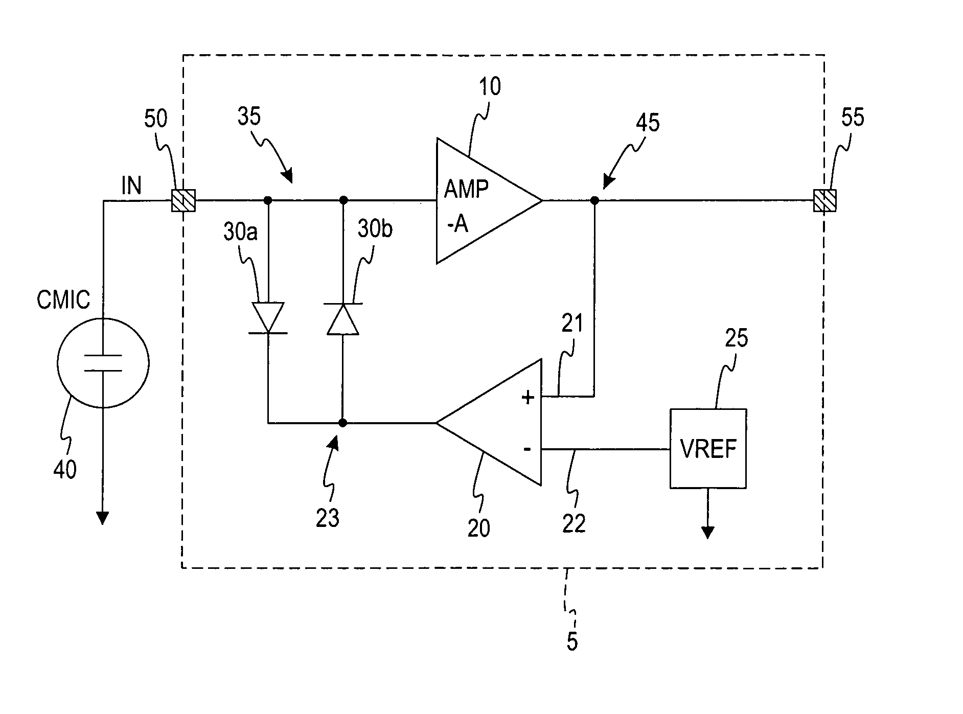
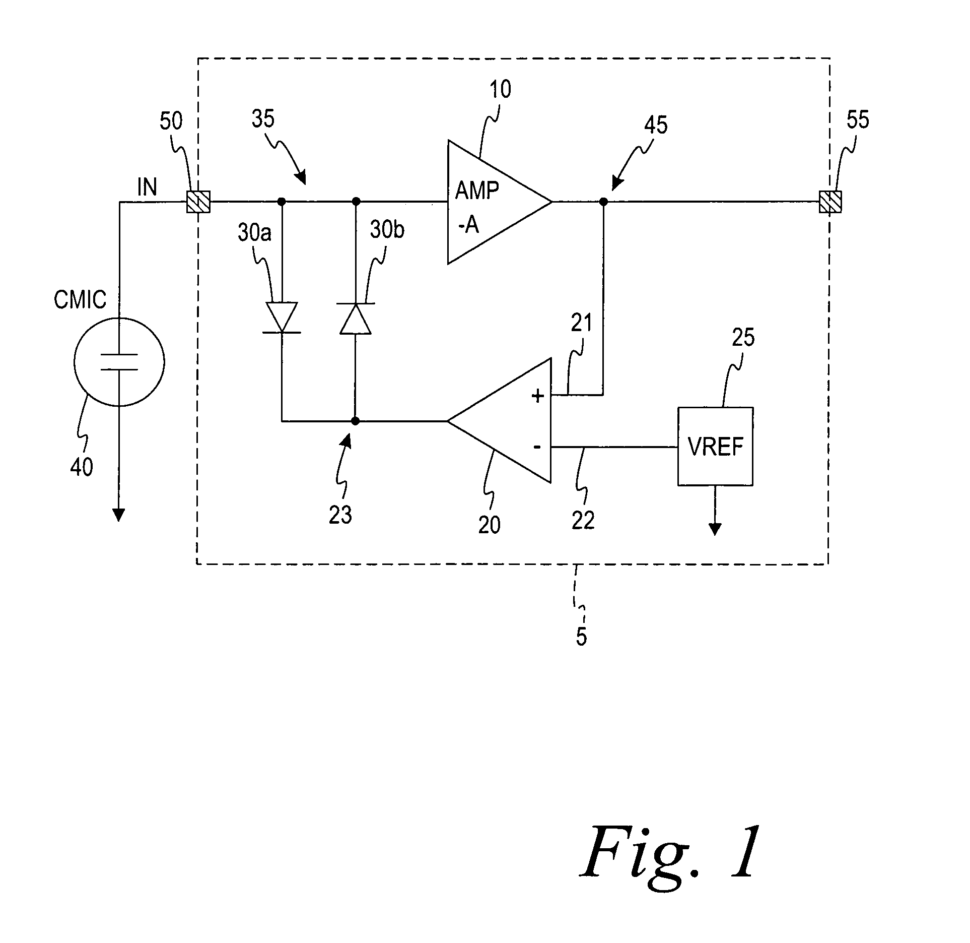
[0030]FIG. 1 shows a condenser transducer element 40 of a miniature microphone coupled to an amplifier circuit integrated on a monolithic integrated die 5. According to the present embodiment of the invention, the condenser transducer element 40 comprises a MEMS-fabricated transducer of silicon base material, but the invention is equally applicable to microphones based for example on electret transducer ele-elements that relies on a pre-deposited electrical charge layer of one or both transducer plates.

[0031]The amplifier circuit comprises an inverting preamplifier 10 and a differential servo amplifier 20 which has a first input connected to an output of the inverting preamplifier 45 and a second input connected to a reference voltage, VREF, generator 25. A non-linear device (30a, 30b) is coupled between an output terminal 23 of the differential servo amplifier 20 and an input node or terminal 35 of the inverting preamplifier 10. The non-linear device comprises a pair of cross-coupl...


PUM

PropertyMeasurementUnit
input resistanceaaaaaaaaaa
time constantaaaaaaaaaa
input impedanceaaaaaaaaaa

Abstract

An amplifier circuit for capacitive transducers, such as miniature electret or condenser microphones, wherein the amplifier circuit comprises bias control means adapted to improve settling of the amplifier circuit. Another aspect of the invention relates to a miniature condenser microphone and a monolithic integrated circuit comprising an amplifier circuit according to the present invention. The present invention provides amplifier circuits of improved performance by resolving traditionally conflicting requirements of maintaining a large input resistance of the amplifier circuit to optimize its noise performance and provide fast settling of the amplifier circuit.

Description

CROSS-REFERENCE To RELATED APPLICATION[0001]This application claims priority to U.S. Provisional Application Ser. No. 60 / 535,879, filed Jan. 12, 2004.FIELD OF THE INVENTION[0002]The present invention relates to amplifier circuits for capacitive transducers and miniature condenser microphones comprising such amplifier circuits, wherein the amplifier circuit comprises bias control means adapted to reduce settling time of a combined amplifier and capacitive transducer assembly.[0003]Amplifier circuits in accordance with the present invention are particularly well-suited for amplifying audio signals generated by miniature condenser microphones used in compact portable communication equipment such as mobile terminals and hearing prostheses.BACKGROUND OF THE INVENTION[0004]Prior art amplifier circuits for capacitive transducers suffer from an unfortunate and inconvenient trade-off between low noise and fast settling time, i.e., the period of time the amplifier circuit requires for reachin...

Claims


Application Information

Patent Timeline
Patent Type & Authority Patents(United States)
IPC IPC(8): H04R3/00H03F1/26H03F1/30H03F3/181H03F3/187
CPCH03F1/30H03F3/187H03F1/305H03F1/301B23H9/16B23H1/04B23H11/00
Inventor FALLESEN, CARSTEN
Owner TDK CORPARATION
Why Eureka
Try Eureka