Apparatus and method for high efficiency operation of a high temperature fuel cell system

a fuel cell and high-efficiency technology, applied in the field of high-temperature fuel cells, can solve the problems of reducing the efficiency of the system, wasting fuel in full combustion, and creating additional heat, and achieves high atomic oxygen/carbon, high efficiency operation, and reduced total air flow and endothermic reforming

Active Publication Date: 2010-03-09
APTIV TECH LTD
View PDF10 Cites 14 Cited by
  • Summary
  • Abstract
  • Description
  • Claims
  • Application Information

AI Technical Summary

Benefits of technology

[0011]Briefly described, a method for operating a hydrocarbon catalytic reformer and close-coupled fuel cell system in accordance with the invention comprises recycling a high percentage of anode syngas into the reformer, preferably in excess of 60%, and as high as 95%. Although air must be supplied to the reformer at start-up, after the system reaches equilibrium operating conditions some or all of the oxygen required for reforming of hydrocarbon fuel is derived from endothermically reformed water and carbon dioxide in the syngas. The recycle rate is considerably higher than the minimum required to supply these oxidants to the fuel. However, the high atomic oxygen / carbon ratio allows lower reforming temperature, in the range of about 650° C. to 750° C., without carbon formation, even with heavy fuels such as gasoline, diesel, or jet fuel. This temperature is sufficiently lower than the stack exit temperature of about 800° C. to 880° C. or higher that most or all of the required endotherm can be provided by the sensible heat of the recycled syngas.
[0012]The high stack exit temperature is achieved by having approximately equal cooling from the anode and cathode sides of the stack. The cathode air flow is significantly reduced over that of the prior art. Overheating of elements within the stack is prevented by configuring the approximately equal anode and cathode gas flows in opposite directions through their respective gas spaces (“counterflow”), such that entering reformate cools the exiting region of the cathode and exiting cathode air, and entering cathode air cools the exiting region of the anode and the exiting syngas. This is a significant improvement over the prior art cross-flow or co-flow arrangements which inherently have an area of the stack and gas seals running undesirably close to, or even above, the syngas exit temperature.
[0013]Using a 90% syngas recycle in accordance with the invention, system fuel efficiencies greater than 50% may be achieved, as well as increased power density in the fuel cell stack, improved stack cooling, lower parasitic losses in air supply, more efficient reforming, and reduced cathode air and reformer heat exchanger sizes.

Problems solved by technology

Such full combustion is wasteful of fuel and creates additional heat which must be removed from the reformate and / or stack, typically by passing a superabundance of cooling air through the cathode side of the stack.
wherein the oxygen / carbon atomic ratio is still 1.0 and the reformate temperature is still about 1000° C. The disadvantages of this process for providing reformate for operating a fuel cell are 1) a continuous water supply must be provided; 2) heat must be provided, typically in the form of burned fuel, thus reducing the efficiency of the system; and 3) the reforming temperature is hard on the reformer materials and catalyst.
However, such high temperatures may be deleterious to the reformer over a period of time, and tend to lower system efficiency.
As previously noted, in endothermic reforming of recycled syngas with modest recycle rates, the reformate produced cannot be cooled much below stack temperature without risk of carbon nucleation.
This creates an added energy parasitic to the stack in the form of a very large air blower, and also tends to make the size of the cathode heat exchanger much larger than would otherwise be necessary.

Method used


Image

  • Apparatus and method for high efficiency operation of a high temperature fuel cell system
  • Apparatus and method for high efficiency operation of a high temperature fuel cell system

Examples


Embodiment Construction

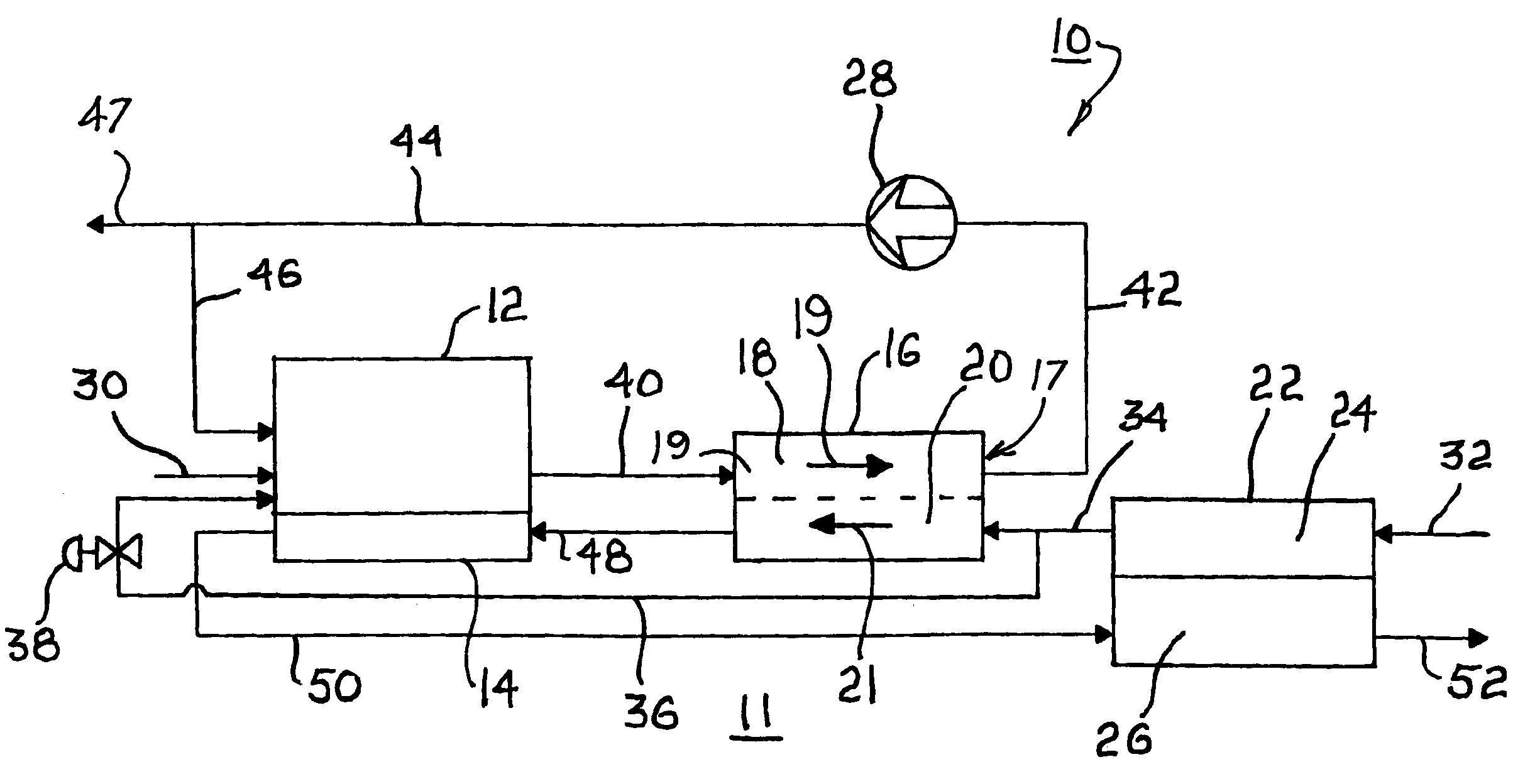
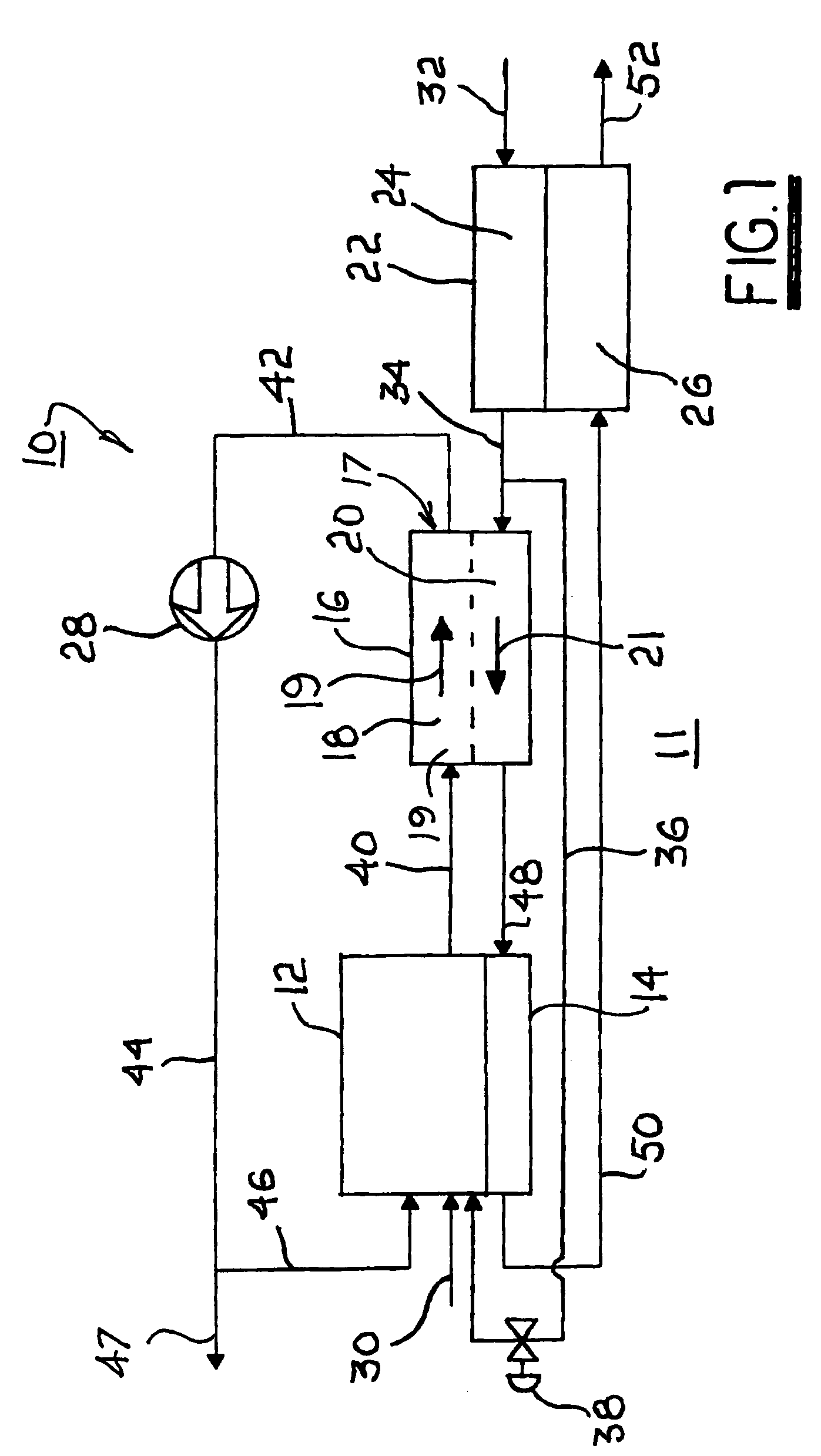
[0015]Referring to FIG. 1, a high temperature fuel cell system 10 as may be suited to use as an auxiliary power unit (APU) in a vehicle 11 includes components known in the art of solid-oxide or molten carbonate fuel cell systems. FIG. 1 is not a comprehensive diagram of all components required for operation but includes only those components novelly formed and / or arranged in accordance with the apparatus and method of the invention. Missing components will be readily inferred by those of ordinary skill in the art.

[0016]A hydrocarbon catalytic reformer 12 includes a heat exchanger 14, preferably formed integrally therewith. A fuel cell stack 16 comprises preferably a plurality of individual fuel cell elements 17 connected electrically in series as is known in the art. Stack 16 includes passageways for passage of reformate across the anode surfaces of stack anodes 19, the passageways being shown collectively and schematically as passageway 18. Stack 16 also includes passageways for pa...


PUM

PropertyMeasurementUnit
temperatureaaaaaaaaaa

Abstract

Apparatus and method for operating a fuel cell system including a hydrocarbon catalytic reformer and close-coupled fuel cell stack by recycling anode syngas into the reformer in a range between 60% and 95% of the total syngas. At equilibrium conditions, oxygen required for reforming of hydrocarbon fuel is derived from endothermically reformed water and carbon dioxide in the syngas. Reforming temperature is between about 650° C. to 750° C. The stack exit temperature is about 800° C. to 880° C. such that the required endotherm can be provided by the sensible heat of the recycled syngas. The stack has approximately equal anode and cathode gas flows in opposite directions, resulting in cooling from both the anodes and cathodes.

Description

TECHNICAL FIELD[0001]The present invention relates to high temperature fuel cells having a solid-oxide electrolytic layer separating an anode layer from a cathode layer; more particularly, to high temperature fuel cell systems comprising a plurality of individual fuel cells in a stack wherein fuel is provided by an associated catalytic hydrocarbon reformer; and most particularly, to such a fuel cell system wherein steady-state reforming is substantially endothermic and wherein a high percentage of the anode tail gas is recycled through the reformer to improve system efficiency.BACKGROUND OF THE INVENTION[0002]Fuel cells which generate electric current by controllably combining elemental hydrogen and oxygen are well known. In one form of such a fuel cell, an anodic layer and a cathodic layer are separated by a non-permeable electrolyte formed of a ceramic solid oxide. Such a fuel cell is known in the art as a “solid-oxide fuel cell” (SOFC). It is further known to combine a plurality ...

Claims


Application Information

Patent Timeline
Patent Type & Authority Patents(United States)
IPC IPC(8): H01M8/06C01B3/38H01M8/04H01M8/12H01M8/14
CPCC01B3/38C01B3/382H01M8/04014H01M8/04097H01M8/0618C01B2203/0233C01B2203/0238C01B2203/0244C01B2203/066C01B2203/1247C01B2203/148H01M2008/1293H01M2008/147Y02E60/50Y02E60/525Y02E60/526Y02P20/129Y02P20/141
Inventor GRIEVE, MALCOLM J.MACBAIN, JOHN A.RAJASHEKARA, KAUSHIKALEXANDER, GREGORY W.
Owner APTIV TECH LTD
Why Eureka
Try Eureka