
Electrochemical device

a technology of electrochemical devices and electrodes, which is applied in the direction of non-aqueous electrolyte cells, cell components, electrochemical generators, etc., can solve the problems of deteriorating charge-discharge cycle characteristics of secondary batteries, impaired incombustibility of nonaqueous electrolyte, etc., and achieve excellent charge-discharge cycle characteristics and incombustibility

Inactive Publication Date: 2010-03-23
KK TOSHIBA
View PDF7 Cites 6 Cited by
  • Summary
  • Abstract
  • Description
  • Claims
  • Application Information

AI Technical Summary

Benefits of technology

The present invention provides an electrochemical device that is incombustible and has good charge-discharge cycle characteristics. The device includes a case, a nonaqueous electrolyte containing a room temperature molten salt, and a first electrode and a second electrode. The second electrode contains a substance with a lamellar crystal structure. The invention also includes specific substituents for the carbonic acid ester group and the acyclic structure. The technical effects of the invention are improved safety and performance of the electrochemical device.

Problems solved by technology

However, in the case of a lithium ion secondary battery using a substance having a lamellar crystal structure, which is represented by a carbonaceous material, as a negative electrode active material, the cationic component of the room temperature molten salt is subjected to a decomposition reaction in the charging stage of the secondary battery, with the result that charge-discharge cycle characteristics of the secondary battery are deteriorated.
However, EC, VC, etc. are incapable of forming a film in an amount conforming to the addition amount.
It should be noted in this connection that EC, VC, etc. are combustible so that it gives rise to the problem that the incombustibility of the nonaqueous electrolyte is impaired.
However, it was impossible to obtain excellent charge-discharge cycle characteristics by using the electrolyte disclosed in the patent document quoted above.

Method used


Image

  • Electrochemical device
  • Electrochemical device
  • Electrochemical device

Examples


first embodiment

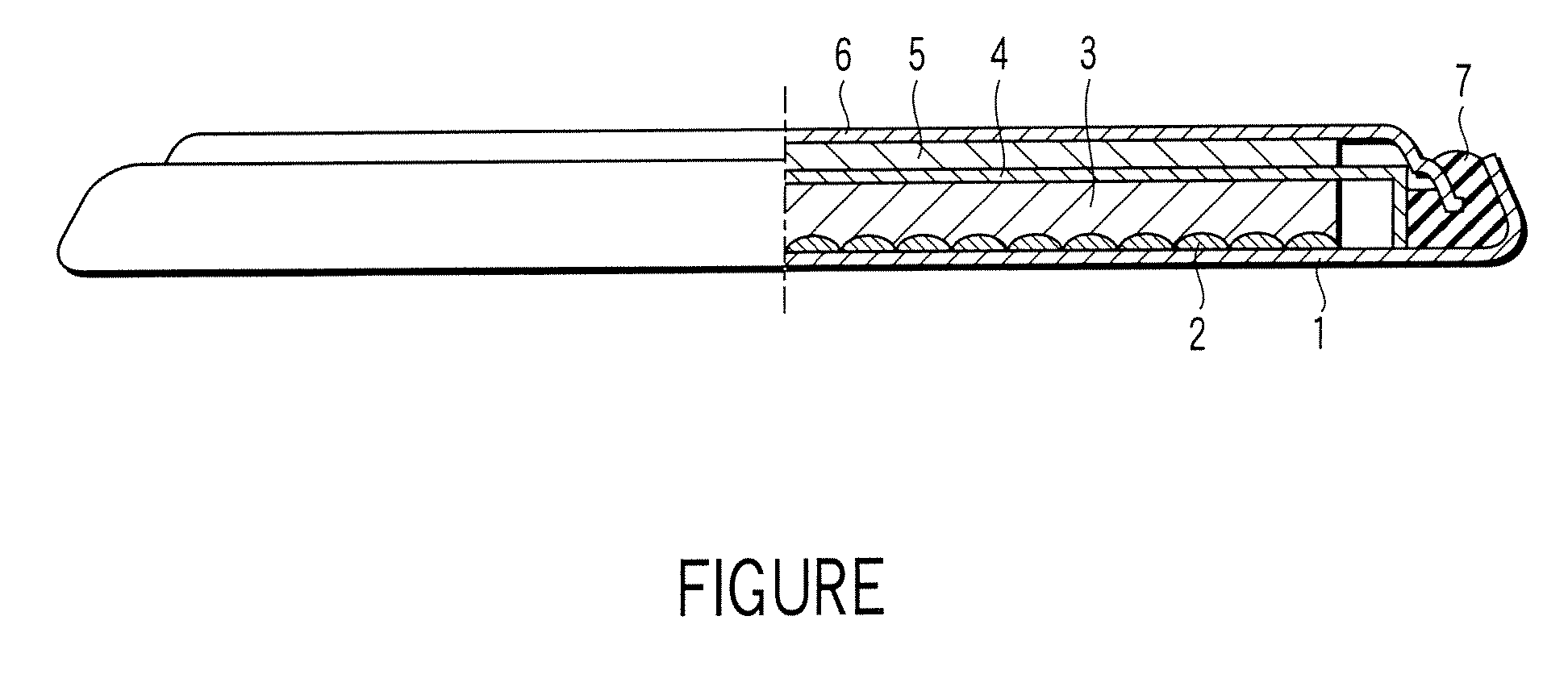
[0027]A lithium ion secondary battery according to a first embodiment of the present invention will now be described with reference to FIGURE. Specifically, FIGURE is a cross sectional view, partly broken away, schematically showing the construction of a lithium ion secondary battery according to the first embodiment of the present invention. Incidentally, the lithium ion secondary battery showing in FIGURE is in coin shape.

[0028]As shown in the drawing, the lithium ion secondary battery comprises a case 1. A positive electrode current collector 2 is placed on the inner bottom of the case 1. Also, a positive electrode 3 is housed in the case 1. The positive electrode 3 is electrically connected to the case 1 via the positive electrode current collector 2. On the other hand, a negative electrode 5 is electrically connected to a negative electrode sealing plate 6 that also acts as a negative electrode current collector. The negative electrode sealing plate 6 is fixed to an opening of ...

second embodiment

[0110]An electric double layer capacitor according to a second embodiment of the present invention will now be described with reference to FIGURE. Incidentally, the following description covers only the portion differing from the first embodiment.

[0111]The electric double layer capacitor has a construction similar to that of the lithium ion secondary battery shown in FIGURE. For example, in the case of the electric double layer capacitor, each of the positive electrode 3 and the negative electrode 5 corresponds to a polarizable electrode. In view of the aspect of improving the energy density, it is desirable for the polarizable electrodes respectively corresponding to the positive electrode 3 and the negative electrode 5 to have substantially the same volume. Incidentally, in the case of the electric double layer capacitor, each of the positive electrode current collector 2 and the negative electrode current collector 6 corresponds to a collection electrode.

[0112]Each of the polariz...

example 1

[0115]Reaction was carried out at room temperature for 6 hours between 4-chloro-1,3-dioxolan-2-one (compound A) and dimethyl ethyl amine (compound B) within acetonitrile. Then, acetonitrile was evaporated until the volume of the reaction mixture was decreased to ½ the original volume. Further, ethyl acetate was added to the reaction mixture, followed by filtering the resultant precipitate and subsequently drying the precipitate under a reduced pressure. In the next step, reaction was carried out at room temperature for 6 hours between the powder obtained by the drying under the reduced pressure and LiTFSI (compound C) within acetonitrile. The resultant precipitate was removed, and the acetonitrile solution was evaporated under a reduced pressure so as to obtain a room temperature molten salt represented by formula (11) given below.

[0116]Incidentally, it is possible to decrease the amount of the impurities contained in the room temperature molten salt by using AgTFSI in place of LITF...


PUM

PropertyMeasurementUnit
temperatureaaaaaaaaaa
interplanar spacing d002aaaaaaaaaa

Abstract

An electrochemical device includes a case, a nonaqueous electrolyte filled in the case and containing a room temperature molten salt in an amount of 1 to 50 vol %, a first electrode housed in the case, and a second electrode housed in the case and containing a substance having a lamellar crystal structure. The room temperature molten salt contains a cation represented by formula (1) or formula (2) given below.R1 includes a carbonic acid ester group. Each of R2 and R3 denotes a substituent having an acyclic structure and having 4 or less carbon atoms, or R2 and R3 are combined to denote a substituent having a cyclic structure and having 4 or 5 carbon atoms.R4 includes a carbonic acid ester group, R5 has an acyclic structure and has 4 or less carbon atoms, and R6 denotes a hydrogen atom or a methyl group.

Description

CROSS-REFERENCE TO RELATED APPLICATIONS[0001]This application is based upon and claims the benefit of priority from prior Japanese Patent Application No. 2005-077074, filed Mar. 17, 2005, the entire contents of which are incorporated herein by reference.BACKGROUND OF THE INVENTION[0002]1. Field of the Invention[0003]The present invention relates to an electrochemical device.[0004]2. Description of the Related Art[0005]In recent years, a lithium ion secondary battery or an electric double layer capacitor is promising as an electrochemical device used as a power source of, for example, electronic equipment or a vehicle.[0006]An organic solvent based nonaqueous electrolyte prepared by dissolving an electrolyte in an organic solvent is used mainly as an nonaqueous electrolyte included in the electrochemical devices referred to above. It should be noted that the organic solvent is combustible. Therefore, in view of the improvement of the safety, various safety devices are mounted to an e...

Claims


Application Information

Patent Timeline
Patent Type & Authority Patents(United States)
IPC IPC(8): H01M6/04H01M10/05H01G9/035H01G11/06H01G11/14H01G11/22H01G11/24H01G11/30H01G11/32H01G11/38H01G11/40H01G11/44H01G11/46H01G11/54H01G11/62H01G11/86H01M10/052H01M10/0567H01M10/0568
CPCH01G9/038H01G9/058H01G11/62H01M4/133H01M10/0525H01M10/0568H01M4/131H01M4/587H01M2300/0022Y02E60/122Y02E60/13Y02E60/10H01G11/22
Inventor KUBOKI, TAKASHITAKAMI, NORIO
Owner KK TOSHIBA
Learn More