Multi-layer decoupling and sealing system

a sealing system and multi-layer technology, applied in the direction of synthetic resin layered products, flooring, transportation and packaging, etc., can solve the problems of damage to the building itself, expensive repair work, and the inability to avoid the diminished reliability of this type of paving

Active Publication Date: 2010-04-20
BLANKE
View PDF16 Cites 3 Cited by
  • Summary
  • Abstract
  • Description
  • Claims
  • Application Information

AI Technical Summary

Benefits of technology

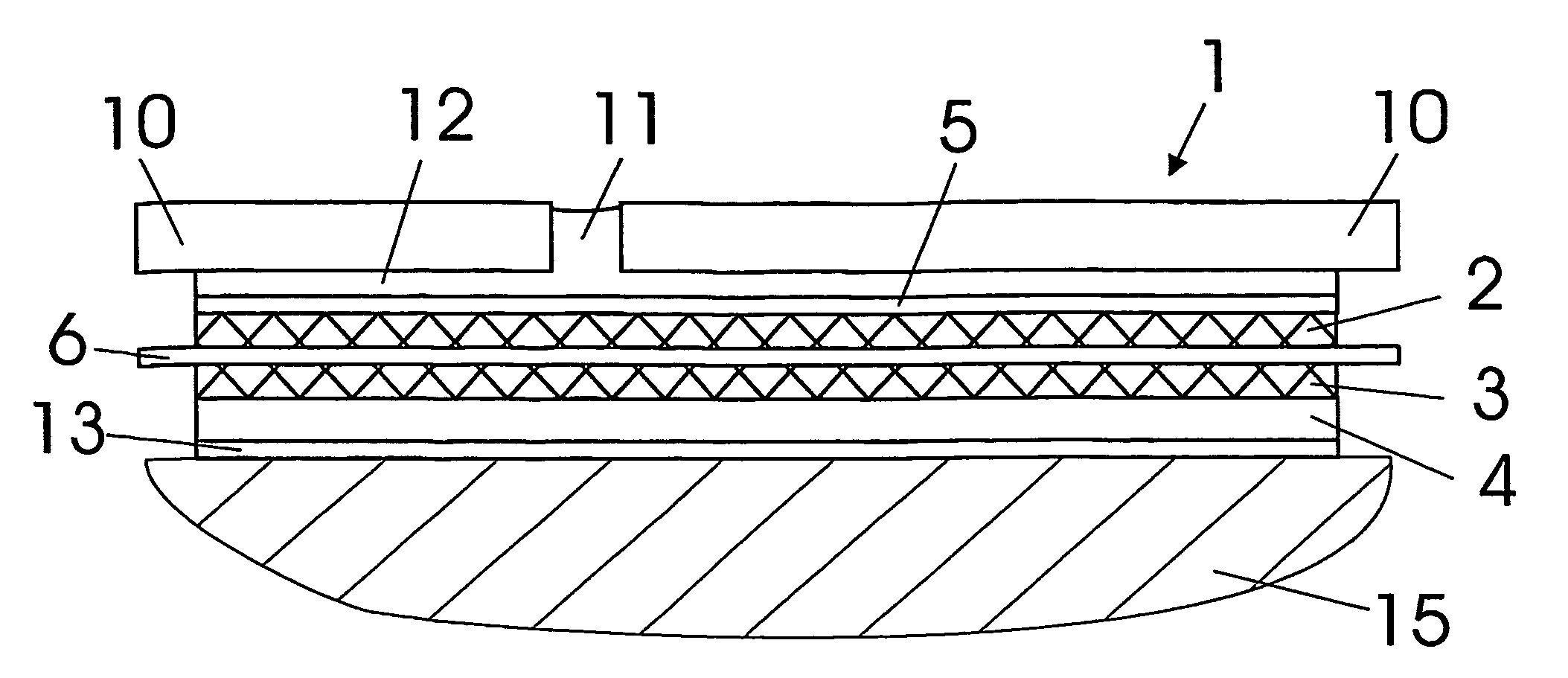
[0009]The present invention describes a multilayer decoupling and sealing system, used in particular for laying ceramic tiles using a thin-bed method, which is of a layered construction that consists, listed from bottom to top, with a liquid-impermeable sealing layer, an anchoring layer formed by a lattice-type structural element for a filler material that is to be incorporated into the upper face of the decoupling and sealing system, which is plastic during processing and subsequently cures; and a reinforcing layer that is fixed, at least in some sections, to the anchoring layer. In particular because of the anchoring layer that is disposed on top and the reinforcing layer that is laid on top of and secured to it, it is ensured that joint mortar that is applied to the top face bonds completely with the decoupling and sealing system, thereby ensuring appropriate load-bearing capacity for the decoupling and sealing system. The lattice-type structural element permits particularly simple construction of the anchoring layer that essentially determines the thickness of the decoupling and sealing system. The sealing layer ensures appropriate liquid-impermeable sealing against the substratum at the installation site, and also ensures mechanical decoupling in the case of floating installation.
[0010]In a first configuration, provision can also be made such that the lattice-type structural element is formed from individual rods that are disposed relative to one another in the form of a lattice and secured to one another at the intersection points of the lattice. A lattice-type structural element of this kind can be manufactured very simply from identical, prefabricated individual rods, and for this reason it is possible to use individual rods that have been extruded cost effectively and wound onto drums and in each instance are positioned relative to each other for the production of the lattice-type structural elements. This makes production of such a lattice-type structural element both cost effective and simple. Unlike the case with other known decoupling and sealing systems, no costly tools have to be made in order to manufacture areas that are angled relative to one another and formed in other ways. In another embodiment, provision is made such that the individual rods of the lattice-type structural element are of an essentially rectangular cross section. In particular, if the edges of the individual rods are of unequal dimensions, the thickness of the lattice-type structural elements can be modified very simply and matched to various requirements.
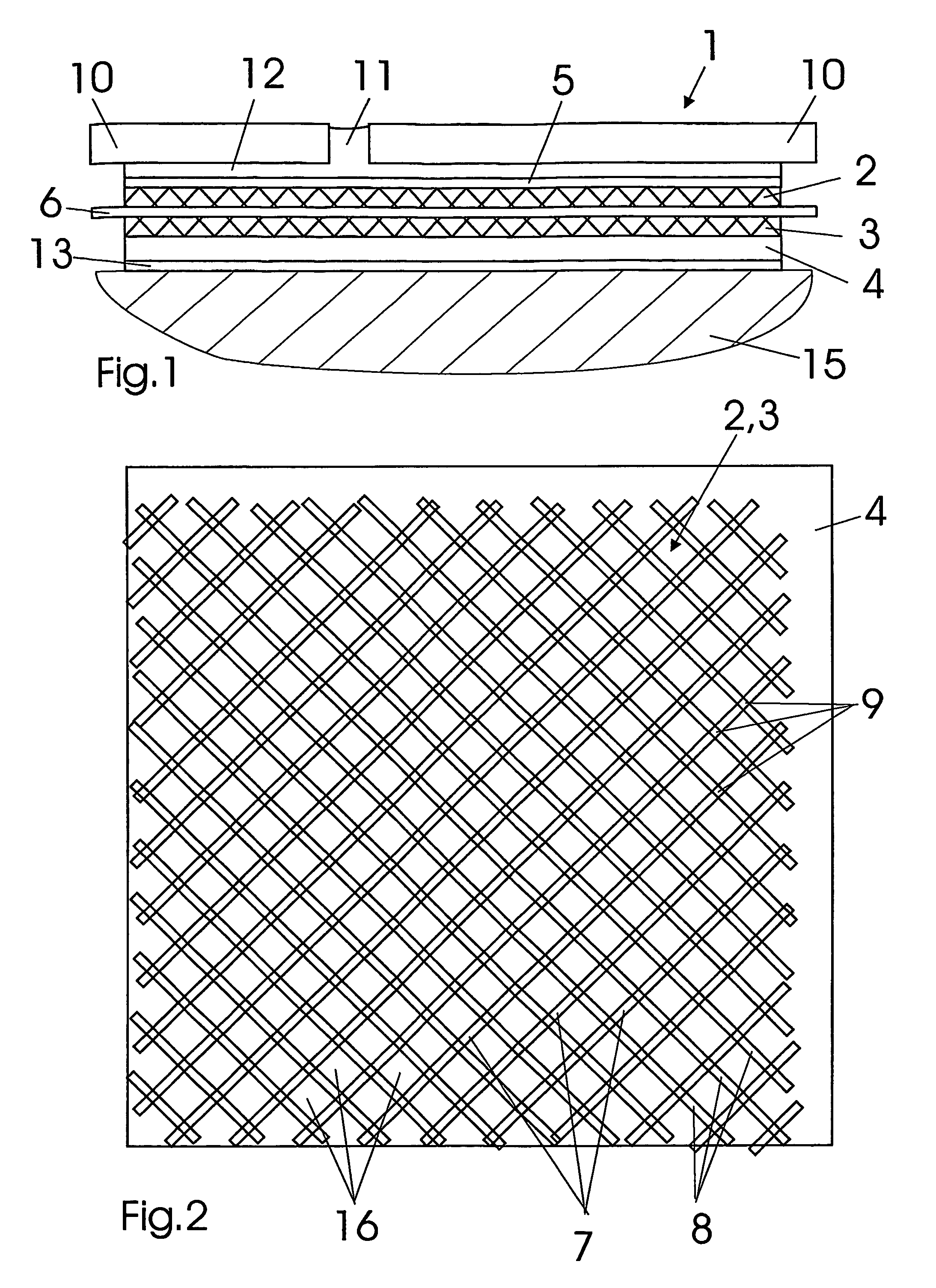
[0011]It is a particular advantage if the intersecting individual rods of the lattice-type structural elements are so arranged that a first layer consists of identically oriented individual rods arranged beneath a second layer of individual rods disposed at an angle relative to the first rods and that are oriented identically to each other. This eliminates the need to warp the individual rods to one another during production, as is the case with textile fabrics; this further simplifies the production process and ensures that corresponding open spaces are formed between the identical layers of the lower and upper courses of individual rods, so that these spaces can be used for incorporating the filler material. It is also conceivable that the lattice-type structure of individual rods be in the form of a rhombus, a rectangle, or a square. Other geometrical shapes can be also be used.

Problems solved by technology

This method, which is satisfactory for interior applications, is problematic when ceramic paving is to be laid in an exterior area, because the effects of moisture and temperature on paving of this kind frequently result in the gradual destruction of the tiles or the base in which they are laid, and it becomes impossible to avoid the diminished reliability of this type of paving, with the result that costly repair work may be required.
Moisture that penetrates through the tile paving into the substratum frequently results in damage to the building itself because the moisture cannot escape easily.
In addition to the foregoing, it is difficult to control the crack behaviour of the ceramic paving and of the substratum because of the very different coefficients of expansion of the substratum, the thin-bed mortar, and the ceramic paving, which are brought about by the very high temperature differences between the high temperatures caused by solar radiation and the low temperatures caused by frost that occur in the exterior area.
For this reason, there is frequently cracking in the tile paving if it is joined rigidly to the substratum.
It is true that such decoupling ensures that mechanical decoupling is effected transversely to the area that is paved; it also entails the disadvantage that the mechanical load-bearing capacity of the tile paving is inadequate.
On the one hand, the tiles are not anchored firmly enough to the decoupling system, and on the other hand, the pressure strength of the decoupling system itself is not optimal.
It is true that, within certain limits, this layered construction permits moisture that has penetrated to drain out of the substratum of a tile layer; however, the mechanical load-bearing capacity of a layered, construction of this kind is unsatisfactory since embedding the uppermost non-woven layer in the tile mortar does not permit adequate anchoring or reinforcing function.

Method used


Image

  • Multi-layer decoupling and sealing system
  • Multi-layer decoupling and sealing system
  • Multi-layer decoupling and sealing system

Examples


Embodiment Construction

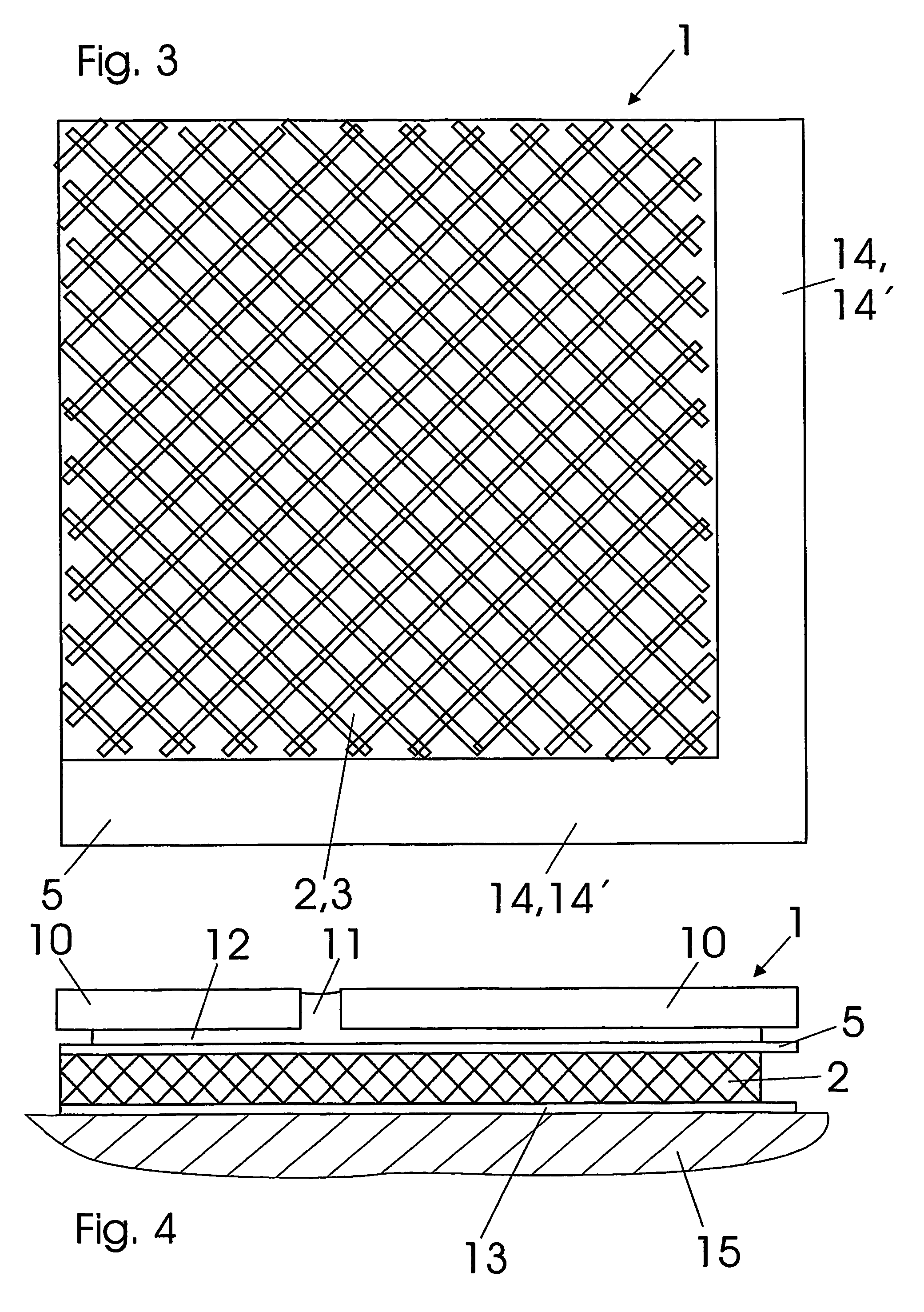
[0030]FIG. 1 is a cross sectional side view that shows the layered structure of a multilayer decoupling and sealing system 1. FIG. 2 is a cross sectional plan view at the level of a sealing layer 4, and FIG. 3 is a plan view of the decoupling and sealing system 1, in cross section along the reinforcing layer 5. In FIG. 1, the decoupling and sealing system 1 according to one embodiment of the present invention is shown installed on a substratum 15, for instance in a cement screed or the like. Tile paving made up of tiles 10 can be seen above the decoupling and sealing system 1, and this is laid in tile mortar 12 by the thin-bed method. The joints 11 between the individual tiles 10 are similarly filled with tile mortar 12.

[0031]The decoupling and sealing system 1 consists of a sealing layer 4 that is applied to the substratum 15 and can, for example, be of polyethylene and can be laid as a strip of predetermined width. The sealing layer4 can be cemented to the substratum 15 and it is ...


PUM

PropertyMeasurementUnit
thicknessaaaaaaaaaa
thicknessaaaaaaaaaa
thicknessaaaaaaaaaa

Abstract

The invention relates to a multi-layer decoupling and sealing system (1), in particular for the laying of ceramic paving (10) according to a thin-bed method (12). Said system comprises a layered construction containing, from the base upwards, a liquid-impermeable sealing layer (4), an anchorage layer (2, 3) that is configured from a lattice-type structural element and that is used to hold a filler material (12), which is to be incorporated into the upper face of the decoupling and sealing system (1) and which is plastic during processing and subsequently cures, in addition to a reinforcement layer (5), which is fixed, at least in some sections, to the anchorage layer (2, 3). This improves the load-bearing capacity of the decoupling and sealing system (1) and the bonding properties of ceramic paving (10) that is laid in a conventional manner on the decoupling and sealing system (1).

Description

RELATED APPLICATIONS[0001]This application is a US National Phase of PCT Application No. PCT / DE2004 / 002470, filed 5 Nov. 2004, which claims priority to German Application Nos. DE 203 17 248.5, filed 6 Nov. 2003 and DE 10 2004 026 652.2, filed 1 Jun. 2004. Each of these applications is herein incorporated in its entirety by reference.FIELD OF THE INVENTION[0002]The present invention relates to a multilayer decoupling and sealing system, in particular for laying ceramic paving by using a thin-bed method.BACKGROUND[0003]Today, ceramic paving, in particular ceramic tiles, is usually laid using the so-called thin-bed method, in which the ceramic paving is laid in a thin, adhesive layer of tile mortar. This method, which is satisfactory for interior applications, is problematic when ceramic paving is to be laid in an exterior area, because the effects of moisture and temperature on paving of this kind frequently result in the gradual destruction of the tiles or the base in which they are ...

Claims


Application Information

Patent Timeline
Patent Type & Authority Patents(United States)
IPC IPC(8): E04F13/08B32B3/22B32B3/24B32B9/04B32B17/02E04D11/02E04F15/02E04F15/08E04F15/18E04F17/00
CPCB32B3/22B32B3/266E04F15/186B32B17/02E04F15/183B32B9/04E04F15/182B32B27/12B32B2307/7246B32B2307/7265B32B7/05
Inventor THRONICKE, SANDRO GERDBLANKE, PETER WILHELM
Owner BLANKE
Why Eureka
Try Eureka