Stirling engine instability detection and prevention

a technology of instability detection and engine, which is applied in the direction of machines/engines, electric generator control, transportation and packaging, etc., can solve the problems of affecting so as to reduce the stroke length of the reciprocating member, accurately determine the stroke length, and ensure the stability of the engin

Inactive Publication Date: 2010-04-27
MICROGEN ENGINE CORP HLDG BV
View PDF15 Cites 9 Cited by
  • Summary
  • Abstract
  • Description
  • Claims
  • Application Information

AI Technical Summary

Benefits of technology

[0014]By monitoring artefacts within a Fourier Transform of the signal from the dchp generator, such as, for example, a fast Fourier Transform (FFT) of the current signal from the alternator as it is fed to a mains grid interface / domestic circuitry, the stability of operation of an engine in the dchp unit can be monitored. If instabilities are detected in that engine (e.g. components such as the piston and cylinder ends / displacer becoming undesirably close and gas spring forces coming into play between them), corrective action can be taken, such as reducing the engine burner firing rate, before full-blown overstroke occurs, and thus preventing damage.
[0021]The measurement of casing acceleration (frequency corrected where necessary) has been found to give a reliable indication of the piston stroke length inside the engine. This in turn allows the derivation of a fully reliable confirmation of impending overstroke.
[0022]The technique of aspects of the invention, for determining the onset of instability (by monitoring a Fourier Transform of the generator output signal) can be usefully combined with the technique of other aspects of the invention, for accurately determining stroke length (by optical or mechanical determination of stroke length). In particular, the combination of these techniques provides for a robust, powerful two stage system that allows for early detection of impending unstable operation of a dchp engine, such as a Linear Free Piston Stirling Engine, and rapid engine shut down where deemed necessary, but with fewer false positives leading to unnecessary engine shutdowns, and fewer false negatives leading to potential engine damage. Thus, in accordance with still a further aspect of the present invention there is provided a dchp system comprising a dchp unit having an engine with a reciprocating member; a combustible fuel supply; a heat output; and a generator for generating an electrical power output; the dchp unit being connected to a mains power supply but operable in the absence thereof; an instability detection apparatus as defined in earlier aspects of this invention; a stroke length detector; and a system controller arranged to receive as a first input from the instability detection apparatus, an indication of the presence of artefacts in the Fourier Transform of the generator output, to receive as a second input from the stroke length indicator the said stroke length detection output; and to control the dchp unit so as to reduce the stroke length of the reciprocating member in dependence upon the first input thereto, the second input thereto, or both.

Problems solved by technology

It is highly undesirable (and potentially damaging) for moving parts of the LFPSE to come into contact with stationary, or other moving parts as a result of piston overstroke.
Repeated collision of moving parts with stationary, or other moving parts will over time cause wear to the components, and apart from reducing the life of the engine, this process also results in small particles (arising from the collision wear) interfering with the narrow internal flow passageways of the engine.
As a consequence, because the piston stroke is unconfined, the amplitude of reciprocation varies as a function of operating conditions and piston overstroke can occur.
This technique suffers from the drawback that the magnet strength may reduce over time, reducing the effectiveness of the magnets as “stops”.
If engine shut-down is mandated upon detection of an overstroke, then false positives result in unnecessary engine shutdowns.
These are at best an irritation (since shutdown stops any heat or power output).
Thus, unnecessary engine shutdowns are also time-consuming.
False negatives are of course even more unacceptable since failure to prevent piston overstroke (through engine shutdown for example) can cause engine damage over time.

Method used


Image

  • Stirling engine instability detection and prevention
  • Stirling engine instability detection and prevention
  • Stirling engine instability detection and prevention

Examples


Embodiment Construction

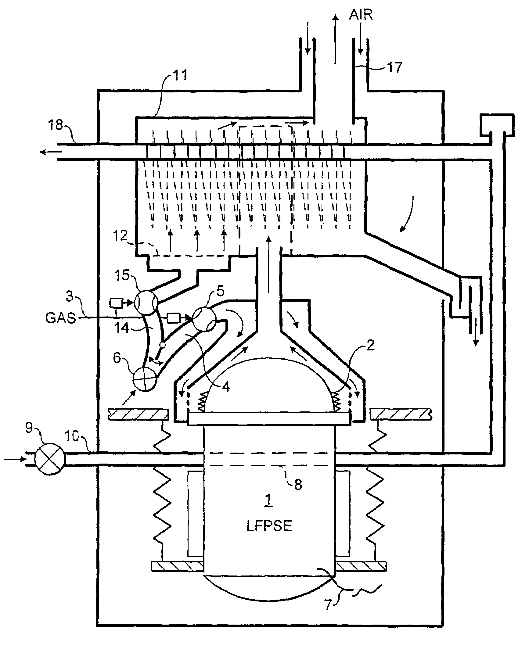
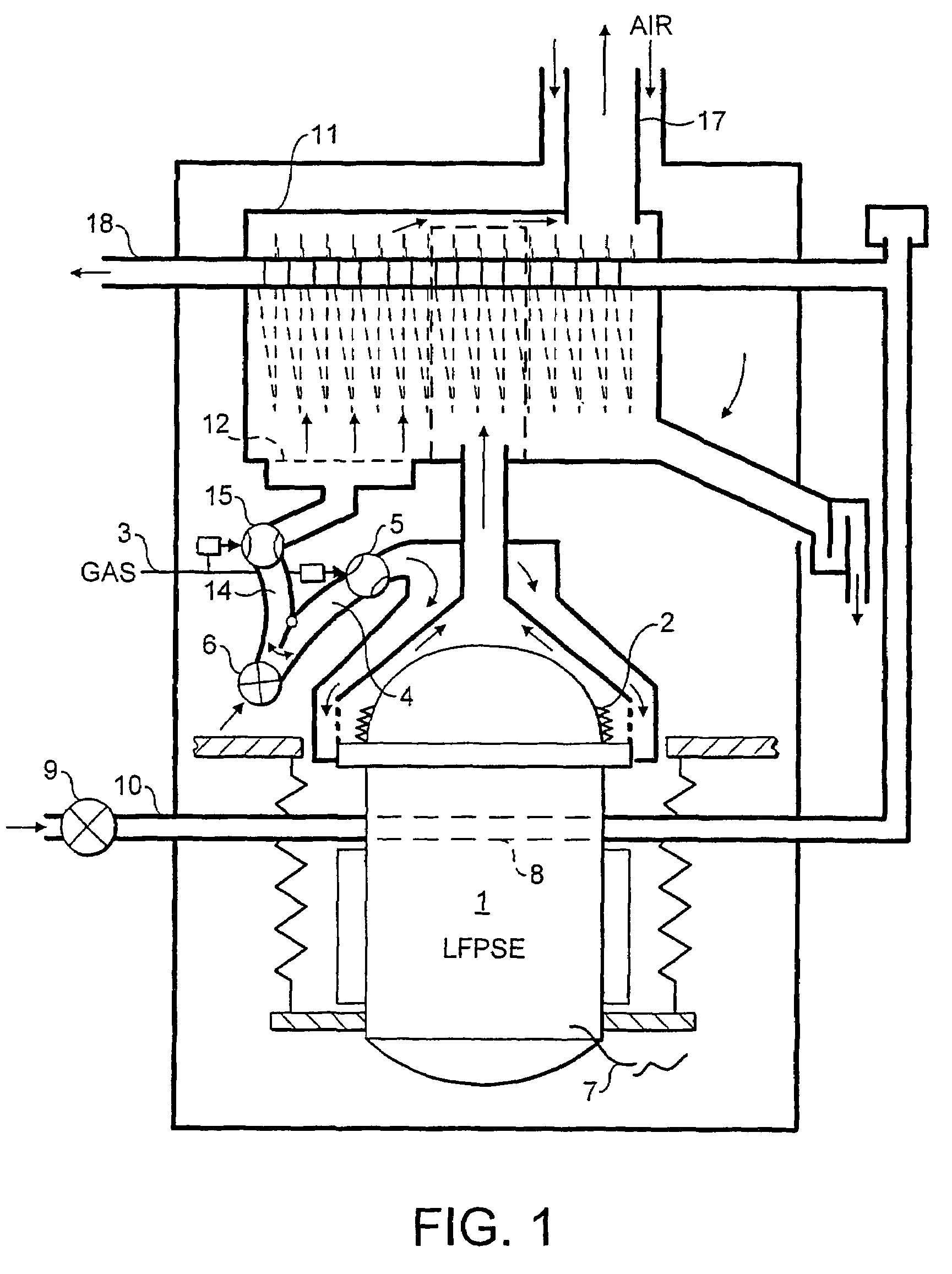
[0034]The dchp system is based around a Stirling engine 1 as shown in FIG. 1. The engine is preferably a linear free piston Stirling engine the operation of which is well known in the art. For use in a dchp system, the electrical output of the engine should be a single phase output of up to 16 A.

[0035]The Stirling engine 1 is driven by a heat input from engine burner 2. This burner is fuelled by combustible gas supply 3 which is mixed with an air supply 4 under the control of a valve 5. The mixed stream is fed to the burner 2 by a fan 6. This drives the Stirling engine in a manner well known in the art to generate an electrical output 7 from a linear alternator. Heat is extracted from the Stirling engine at cooler 8 which is essentially a heat exchanger through which water is pumped by a pump 9 along line 10. The water passing through the cooler 8 is then further heated in a heat exchanger 11 by exhaust gas from the engine burner which has heated the head of the Stirling engine. In ...


PUM


Abstract

A Stirling engine (1) includes a reciprocating piston which drives an alternator to provide an electrical output (7). The current signal (7) is measured by a current monitor (60) and a fast Fourier Transform value is produced. The FFT of the current signal (7) has been found to be directly related to the stability of operation of the Stirling engine. As harmonic peaks in the FFT increase, this indicates that the stroke length of the piston is approaching or exceeding a safe maximum. Correction action, such as a reduction in heat to the Stirling engine, can be taken in consequence. A variety of stroke length detectors (110) are also disclosed, for use in combination with, or separately from, the FFT analysis of the current signal (7). Optical and mechanical switches and analogue sensors are disclosed, along with an accelerometer mounted upon the casing of the Stirling engine.

Description

CROSS REFERENCE TO RELATED APPLICATIONS[0001]The present application claims priority to Great Britain Patent Application No. 0416330.9 filed Jul. 22, 2004, which application is incorporated herein fully by this reference.FIELD OF THE INVENTION[0002]This invention relates to a method and an apparatus for detecting instabilities in a domestic combined heat and power unit (dchp) and particularly but not exclusively to a method and apparatus for detecting and / or preventing piston overstroke in a linear-free piston Stirling engine in a dchp unit.BACKGROUND OF THE INVENTION[0003]Linear-free piston Stirling engines (LFPSEs) may be employed to generate both heat and power for domestic use. The basic manner of operation of a dchp system incorporating such an LFPSE is detailed in various of our earlier published patent applications—see for example WO-A-03 / 076857.[0004]LFPSEs typically comprise a displacer mounted via a flexible rod to displacer springs. Application of heat to the space above ...

Claims


Application Information

Patent Timeline
Patent Type & Authority Patents(United States)
IPC IPC(8): F01K15/00F01B29/10F02G1/043F02G1/047H02P9/06H02P25/06
CPCF02G1/043F02G1/047H02P9/06H02P25/06F02G2275/10H02P2101/30Y02E20/14F02G2275/20
Inventor SPENCELEY, CHRISTOPHER JOHNSILCOCK, ROGER STUARTALDRIDGE, WAYNE KENNETHMCENTEE, JARLATH MICHAELWELTY, STEPHEN CHARLESSMITH, GORDONHARDINGHAM, CHRISTOPHER MARK
Owner MICROGEN ENGINE CORP HLDG BV
Why Eureka
Try Eureka