Littrow external oscillator semiconductor laser optical axis deviation correction method and device

a diode laser and optical axis correction technology, applied in semiconductor lasers, instruments, nanoinformatics, etc., can solve the problem of optical axis shift depending on wavelength change, and achieve the effect of high performan

Inactive Publication Date: 2010-04-27
JAPAN SCI & TECH CORP
View PDF11 Cites 0 Cited by
  • Summary
  • Abstract
  • Description
  • Claims
  • Application Information

AI Technical Summary

Benefits of technology

[0004]Although the above-described Littrow-type ECDLs are convenient and have high performance with respect to output power etc, there is a disadvantage that the optical axis of the output beam shifts depending on changes of wavelengths.
[0011]However, the Littman-type ECDLs are more complex in the configuration than the Littrow-type ECDLs. Further, the zero-order diffraction light 20 which is the reflected light from the mirror 15 becomes a loss and the output power is decreased. Moreover, the feedback efficiency is decreased since the light returns to the LD 11 after two times of diffractions. As a result, the variable range of wavelength is narrowed.
[0018]In consideration of the above problems, the present invention provides a Littrow-type ECDL optical axis displacement correction method and device to easily, inexpensively, and accurately correct displacement of optical axis in Littrow-type ECDLs.

Problems solved by technology

Although the above-described Littrow-type ECDLs are convenient and have high performance with respect to output power etc, there is a disadvantage that the optical axis of the output beam shifts depending on changes of wavelengths.

Method used


Image

  • Littrow external oscillator semiconductor laser optical axis deviation correction method and device
  • Littrow external oscillator semiconductor laser optical axis deviation correction method and device
  • Littrow external oscillator semiconductor laser optical axis deviation correction method and device

Examples


embodiment

[0029]An embodiment of the present invention is described in detail with reference to the drawings.

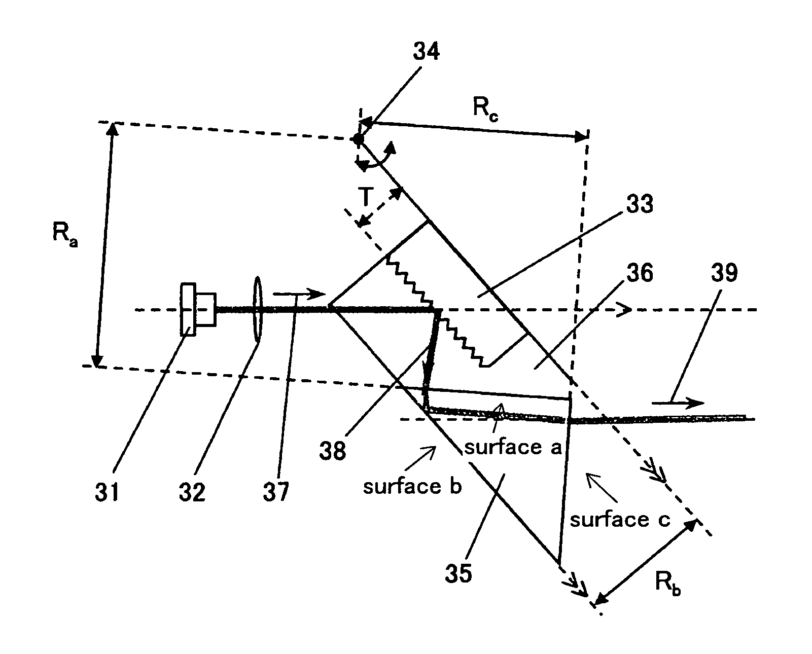
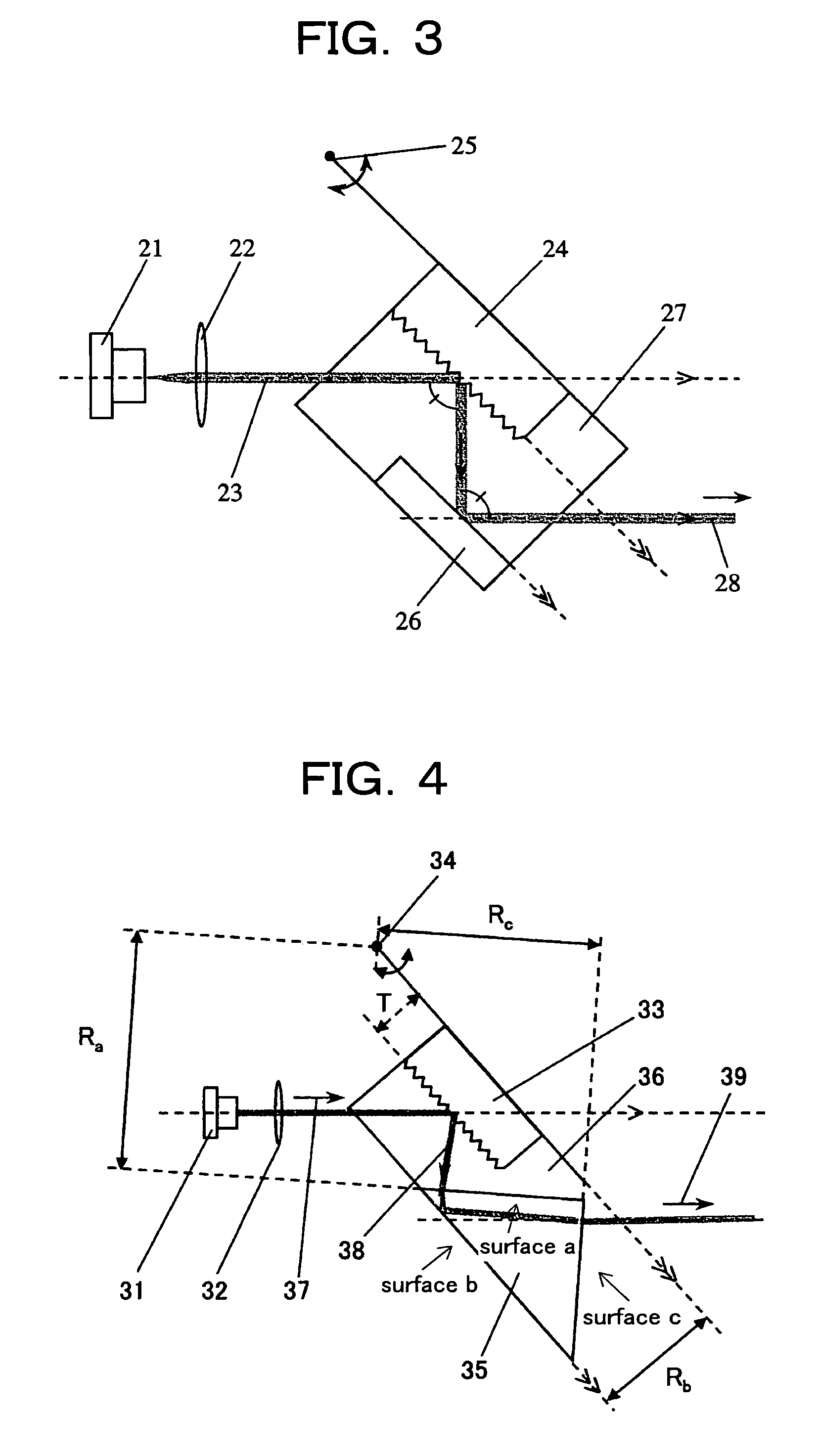
[0030]FIG. 4 is a Littrow-type ECDL which uses a prism according to an embodiment of the present invention.

[0031]In this drawing, reference numeral 31 denotes a laser diode (LD), reference numeral 32 denotes a collimating lens, reference numeral 33 denotes a diffraction grating, reference numeral 34 denotes a rotary shaft of the diffraction grating 33, reference numeral 35 denotes a column-shaped prism having a bottom surface of a right-angled isosceles triangle, reference numeral 36 denotes a jig for fixing the diffraction grating 33 and the prism 35 in a predetermined arrangement (arrangement so that the grating surface of the diffraction grating 33 and surface b which is a hypotenuse of the right-angled isosceles triangle, are parallel to each other), reference numeral 37 denotes an incident light, reference numeral 38 denotes the zero-order diffraction light, and reference numeral ...


PUM


Abstract

A Littrow-type external-cavity diode laser optical axis displacement correction method and device to easily, inexpensively, and accurately correct displacement of optical axis in Littrow-type ECDLs is provided. In the Littrow-type ECDL optical axis displacement correction device and method, a means for introducing a laser beam, a jig 36 for integrally fixing a diffraction grating 33 and a prism 35 into which the laser beam is introduced in a predetermined arrangement, and a rotary shaft 34 capable of integrally rotating the diffraction grating 33 and the prism 35 are included. By the rotation of the diffraction grating 33 and the prism 35 around the rotary shaft 34, the wavelength of the incident light can be changed, and the optical axis of the output light 39 is not changed by the change of the wavelength.

Description

TECHNICAL FIELD[0001]The present invention relates to a Littrow-type external-cavity diode laser optical axis displacement correction method and device.BACKGROUND ART[0002]Tunable lasers have been frequently used in the field of atomic spectroscopy, molecular spectroscopy, laser cooling, semiconductor quantum dot spectroscopy, and in the study of quantum information processing.[0003]As such devices, large dye lasers, ti-sapphire lasers and the like have been commercially available by optical component manufacturers. Recently, more inexpensive and compact external cavity diode laser (ECDLs) have come onto the market. In the ECDLs, there are two types; the Littrow-type and the Littman-type.SUMMARY OF THE INVENTION[0004]Although the above-described Littrow-type ECDLs are convenient and have high performance with respect to output power etc, there is a disadvantage that the optical axis of the output beam shifts depending on changes of wavelengths.[0005]Hereinafter, detailed description...

Claims


Application Information

Patent Timeline
Patent Type & Authority Patents(United States)
IPC IPC(8): H01S3/08H01S5/14
CPCB82Y10/00B82Y20/00H01S5/141H01S5/143H01S5/0071H01S5/005
Inventor TAKAMIZAWA, AKIFUMIEDAMATSU, KEIICHI
Owner JAPAN SCI & TECH CORP
Why Eureka
Try Eureka