Capacitor structure having butting conductive layer

a capacitor and butting technology, applied in the direction of resistors, solid-state devices, basic electric elements, etc., can solve the problems of high manufacturing cost and complex conventional fabrication methods of capacitor structures, and achieve the effect of increasing capacitan

Active Publication Date: 2010-05-04
UNITED MICROELECTRONICS CORP
View PDF12 Cites 3 Cited by
  • Summary
  • Abstract
  • Description
  • Claims
  • Application Information

AI Technical Summary

Benefits of technology

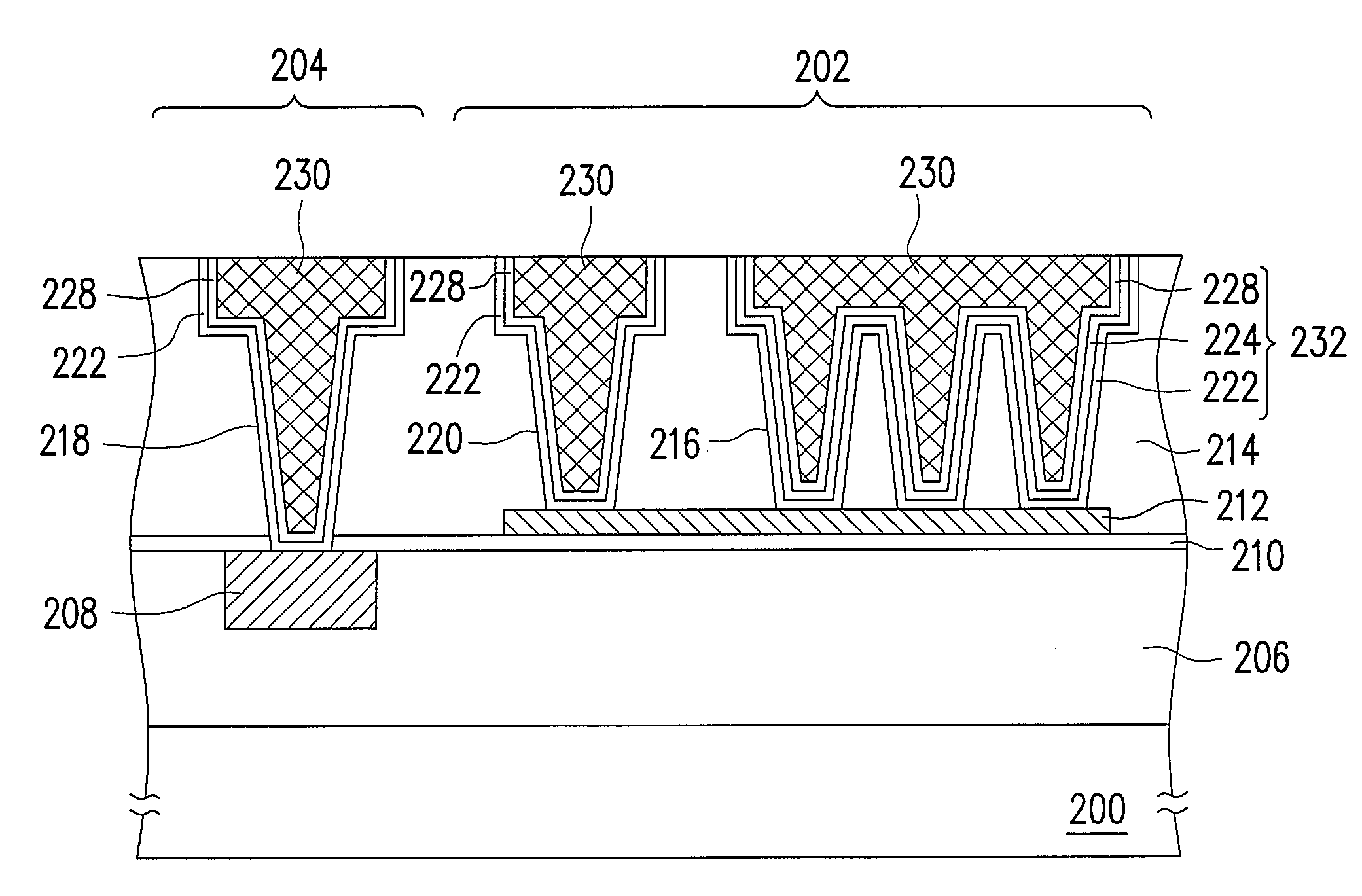
[0008]Accordingly, the present invention is directed to provide a capacitor structure for effectively increasing the capacitance.
[0009]The present invention is also directed to provide a method of fabricating the capacitor structure for reducing the process complexity and manufacturing cost.
[0030]Based on the above, in the capacitor structure of the present invention, the bottom electrode layer and the top electrode layer are formed on the inner wall and the bottom surface of the first opening, so the effective surface area of a vertical portion is increased, thereby improving the capacitance effectively. Moreover, the capacitor structure of the present invention has a butting conductive layer, thereby increasing the flexibility of the design and process.
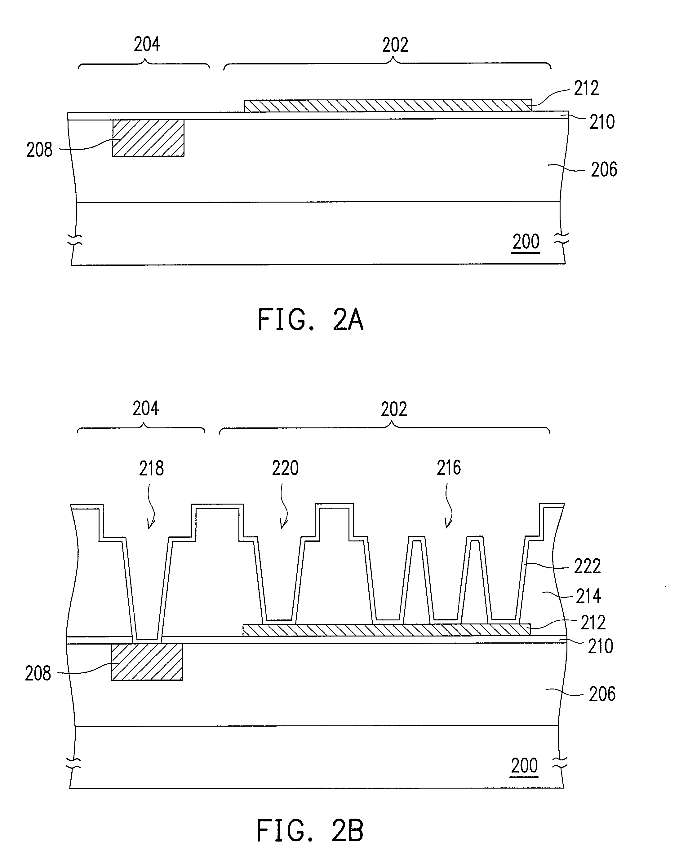
[0031]On the other hand, in the method of fabricating a capacitor structure of the present invention, the first opening in the capacitor region and the second opening in the non-capacitor region are formed by using the same photo mask, and the second metal interconnect layer in the opening is formed at the same time, thereby effectively reducing the process complexity and manufacturing cost.
[0032]Furthermore, when the third opening is formed, the bottom electrode layer may be connected to a bias through the butting conductive layer and the second metal interconnect layer formed in the third opening, thereby further simplify the process.

Problems solved by technology

Therefore, the conventional fabricating method of the capacitor structure is quite complex and more photo masks are used, and thus the manufacturing cost is high.

Method used


Image

  • Capacitor structure having butting conductive layer
  • Capacitor structure having butting conductive layer
  • Capacitor structure having butting conductive layer

Examples


Embodiment Construction

[0038]FIGS. 2A to 2D are cross-sectional views of processes of fabricating a memory structure according to an embodiment of the present invention.

[0039]First, referring to FIG. 2A, a substrate 200 is provided, which includes a capacitor region 202 and a non-capacitor region 204 and has a dielectric layer 206 and a metal interconnect layer 208. The metal interconnect layer 208 is located in the dielectric layer 206 in the non-capacitor region 204. The material of the dielectric layer 206 is, for example, silicon oxide, and depending on the etch, lithography processes and device speed requirements, the material of the dielectric layer 206 may be low-k material, anti-reflective coating material, etch hard mask material or a combination of different dielectric materials. A forming method of the dielectric layer 206 is, for example, a chemical vapor deposition (CVD) process. The material of the metal interconnect layer 208 is, for example, metal, such as copper. A forming method of the m...


PUM


Abstract

A capacitor structure including a substrate, a butting conductive layer, a second dielectric layer, a plurality of openings, a bottom electrode layer, a capacitor dielectric layer, a top electrode layer, and a second metal interconnect layer is provided. The substrate has a first dielectric layer and a first metal interconnect layer located in the first dielectric layer in a non-capacitor region. The butting conductive layer is disposed over the first dielectric layer in a capacitor region. The second dielectric layer is disposed over the first dielectric layer and covers the butting conductive layer. The openings include a first opening exposing a portion of the butting conductive layer and a second opening exposing the first metal interconnect layer. The bottom electrode layer, the capacitor dielectric layer, and the top electrode layer are conformally stacked in the first opening sequentially. The second metal interconnect layer is disposed in the openings.

Description

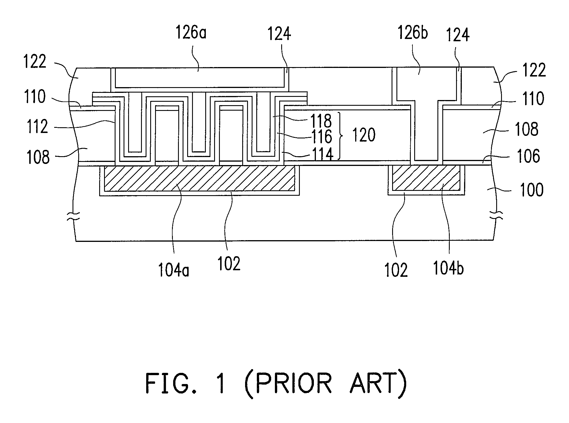
BACKGROUND OF THE INVENTION[0001]1. Field of the Invention[0002]The present invention relates to a semiconductor device structure and a fabricating method thereof, and more particularly to a capacitor structure and a fabricating method thereof.[0003]2. Description of Related Art[0004]Capacitors are indispensable components in an integrated circuit. In the design and process of the capacitors, capacitance and disposal area of the capacitors must be taken into account. Therefore, it is an important topic in the integrated circuit design to propose a capacitor structure having a high integrity and high capacitance in the current integrated circuit process, so as to increase the effective surface area and improve the capacitor performance when the area occupied by the capacitor is gradually reduced.[0005]FIG. 1 is a cross-sectional view of a conventional capacitor structure.[0006]Referring to FIG. 1, the capacitor structure includes dielectric layers 100, 108, 122, barrier layers 102, 1...

Claims


Application Information

Patent Timeline
Patent Type & Authority Patents(United States)
IPC IPC(8): H01L27/108H01L29/76H01L29/94H01L31/119
CPCH01L23/5223H01L28/60H01L2924/0002H01L2924/00
Inventor CHEN, CHUNG-CHIH
Owner UNITED MICROELECTRONICS CORP
Why Eureka
Try Eureka