Composite utility blade, and method of making such a blade

a utility blade and composite technology, applied in the field of utility blades, can solve the problems of affecting the cutting performance of the blade, the cutting edge of such conventional blades is often not as wear resistant, and the entire blade is relatively brittle, etc., to achieve the effect of improving the cutting performance, wear resistance, and hardness of the cutting edg

Inactive Publication Date: 2010-05-11
BLACK & DECKER INC
View PDF70 Cites 19 Cited by
  • Summary
  • Abstract
  • Description
  • Claims
  • Application Information

AI Technical Summary

Benefits of technology

[0030]One advantage of the utility blades of the present invention, is that they provide an extremely hard, wear-resistant cutting edge, and an extremely tough, spring-like backing, particularly in comparison to the conventional utility blades as described above. Thus, the utility blades of the present invention provide significantly improved blade life, and cutting performance throughout the blade life, in comparison to conventional utility blades. In addition, the utility blades, and methods of making such blades, are relatively cost effective, particularly in comparison to the composite utility blades defining sandwiched, laminated and / or coated constructions, as also described above. As a result, the utility blades of the present invention provide a combination of wear resistance, toughness, cutting performance, and cost effectiveness heretofore believed to be commercially unavailable in utility blades.

Problems solved by technology

One of the drawbacks associated with such conventional utility blades is that each blade is formed of a single material, typically carbon steel, which is heat treated to a relatively hard and brittle state, typically about 58 Rc.
Thus, although such blades define a relatively hard, wear-resistant cutting edge, the entire blade is also relatively brittle, and therefore is subject to premature breaking or cracking in use.
In addition, the cutting edges of such conventional blades are frequently not as wear resistant as might otherwise be desired.
However, because the entire blade is made of the same material, any increase in hardness, and thus wear resistance of the cutting edge, would render the blade too brittle for practical use.
As a result, such conventional utility blades are incapable of achieving both the desired wear resistance at the cutting edge, and overall toughness to prevent cracking or premature breakage during use.
Another drawback of such conventional utility blades is that the carbon steel typically used to make such blades corrodes relatively easily, thus requiring premature disposal of the blades and / or costly coatings to prevent such premature corrosion.
One of the drawbacks associated with these laminated, sandwiched and / or coated constructions, is that they are relatively expensive to manufacture, and therefore have not achieved widespread commercial use or acceptance in the utility blade field.
Although such bi-metal band saw blades have achieved widespread commercial use and acceptance over the past 30 years in the band saw blade industry, there is not believed to be any teaching or use in the prior art to manufacture utility blades defining a bi-metal or other composite construction as with bimetal band saw blades.
In addition, there are numerous obstacles preventing the application of such band saw blade technology to the manufacture of utility blades.
However, the relatively tough, spring-like backing used, for example, to manufacture bi-metal band saw blades, can be relatively difficult to score and snap in comparison to conventional carbon steel utility blades.
In addition, the heat treating applied to conventional utility blades could not be used to heat treat bimetal or other composite utility blades.
The high speed or tool steels used to manufacture wear-resistant cutting edges, such as the wear-resistant cutting edges in prior art band saw blades, are relatively expensive in comparison, for example, to the carbon steels used to manufacture conventional utility blades.
In addition, the grinding and honing operations involved in forming wear-resistant cutting edges from high speed and tool steels can create significant amounts of scrap and / or waste of these expensive materials.

Method used


Image

  • Composite utility blade, and method of making such a blade
  • Composite utility blade, and method of making such a blade
  • Composite utility blade, and method of making such a blade

Examples


Embodiment Construction

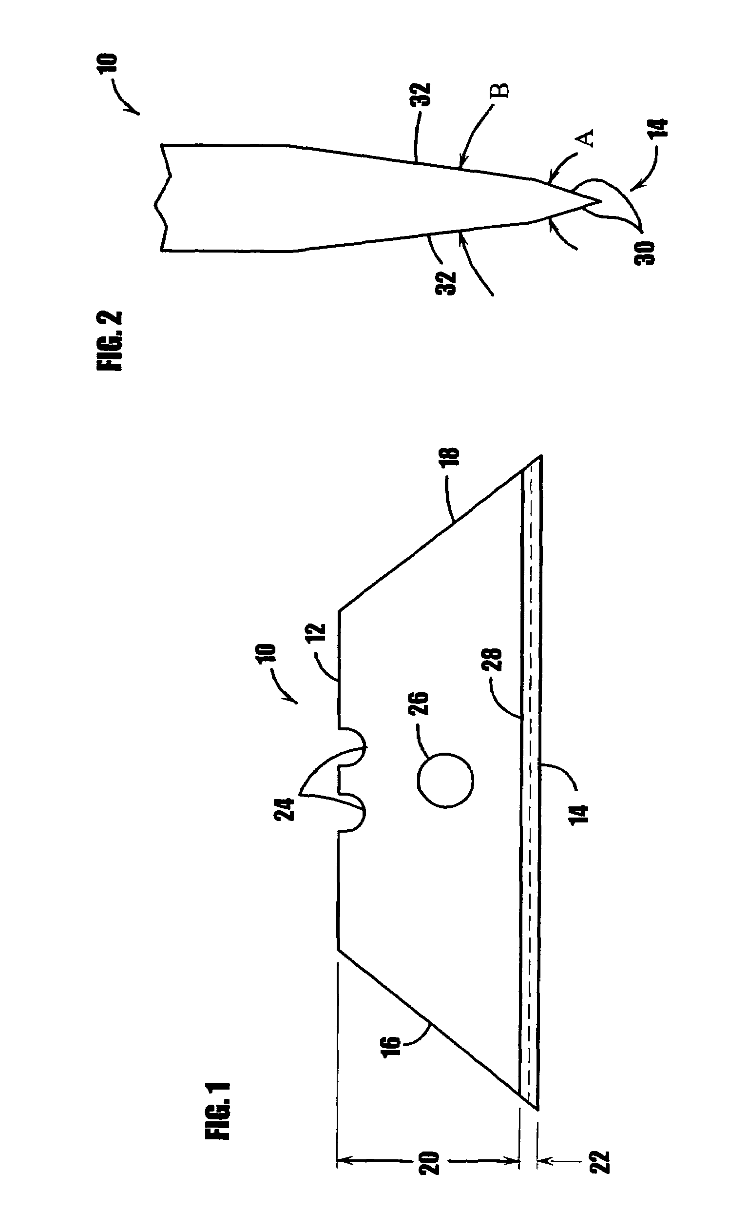
[0046]In FIG. 1, a composite utility blade embodying the present invention is indicated generally by the reference numeral 10. The utility blade 10 defines a back edge 12, a cutting edge 14 located on an opposite side of the blade relative to the back edge, and two side edges 16, 18 located on opposite sides of the blade relative to each other and extending between the back and cutting edges of the blade. As shown typically in FIG. 1, in the illustrated embodiment of the present invention, the back, cutting and side edges of the blade preferably define an approximately trapezoidal peripheral configuration. However, as described further below with reference to FIGS. 11A-11D, the utility blade of the present may take any of numerous different shapes or configurations that currently or later become known, including, for example, a square or parallelogram shape, and / or any desired shape with squared, rounded or oblique cutting corners.

[0047]The blade 10 further defines a first metal por...


PUM

PropertyMeasurementUnit
temperatureaaaaaaaaaa
included angleaaaaaaaaaa

Abstract

A composite utility blade and method of making such a blade involves butt joining a high speed or tool steel wire to a front edge of an alloy steel backing strip. The wire defines a predetermined cross-sectional shape that substantially corresponds to the cross-sectional shape of the cutting edge of the blade. The wire is electron beam welded to the backing strip to form a composite strip defining a first metal portion formed by the alloy steel backing strip, a second metal portion formed by the high speed or tool steel wire, and a weld region joining the first and second metal portions. The composite strip is then annealed, and the annealed strip is straightened to eliminate any camber therein. The annealed composite strip is then hardened such that the first metal portion defines a first surface hardness and the second metal portion defines a second surface hardness greater than the first surface hardness. The hardened strip is then subjected to tempering and quenching cycles, and facets are formed on the edge of the second metal portion to form a straight, tool steel cutting edge. The composite strip is then scored at axially spaced locations to form a plurality of score lines, and the plurality of score lines define a plurality of blade sections there between. The cutting edge may be coated with AlTiN, TiN, or an inner coating of AlTiN and an outer coating of TiN.

Description

CROSS-REFERENCE TO RELATED APPLICATIONS[0001]This patent application claims the benefit of U.S. provisional patent application Ser. No. 60 / 451,985, filed Mar. 5, 2003, entitled “Composite Utility Knife Blade, And Method Of Making Such A Blade”. The foregoing patent application is assigned to the Assignee of the present invention and is hereby expressly incorporated by reference as part of the present disclosure.FIELD OF THE INVENTION[0002]The present invention relates to utility blades, and more particularly, to composite utility blades wherein the outer cutting edge of the blade is made of a highly wear-resistant alloy, and a backing portion of the blade is made of an alloy selected for toughness, such as spring steel. The present invention also relates to methods of making such composite utility blades.BACKGROUND INFORMATION[0003]Conventional utility blades are made of carbon steel and define a back edge, a cutting edge located on an opposite side of the blade relative to the back...

Claims


Application Information

Patent Timeline
Patent Type & Authority Patents(United States)
IPC IPC(8): B26B9/00B23K11/00B32B15/04B21D53/64B21K11/02B26D1/00
CPCB21D53/64B21K11/02B26B9/00B26D1/0006Y10T428/12576B26D2001/002Y10T428/12965
Inventor KORB, WILLIAM B.DOUGLAS, BRIAN K.SUKADHARE, DAYANANDASCOTT, GARY F.
Owner BLACK & DECKER INC
Why Eureka
Try Eureka