Coating apparatus for an aluminum alloy heat exchanger member, method of producing a heat exchanger member, and aluminum alloy heat exchanger member

a technology of heat exchanger and coating apparatus, which is applied in the direction of application, lighting and heating apparatus, soldering apparatus, etc., can solve the problems of poor adhesion of flux after application, increase production cost, and inability to exert objective

Inactive Publication Date: 2010-05-25
FURUKAWA SKY ALUMINUM CORP
View PDF34 Cites 6 Cited by
  • Summary
  • Abstract
  • Description
  • Claims
  • Application Information

AI Technical Summary

Problems solved by technology

However, in this process, the adhesion of flux after applying is poor and thus the flux is flown by hot air that circulated in a furnace.
Therefore, there is a risk of causing a problem in that the desired objective effect would not be exerted.
Further, there are other problems in that floating of un-adhered flux causes at the time of applying the flux worsened working conditions and that the step of applying the flux results in an increase in production cost.
Besides, since an automotive heat exchanger has a detailed complicated configuration, uniform coating of flux is very difficult.
Therefore, there is a problem of inadequate brazing at a portion having an insufficient amount of flux applied, or there is a problem of spoiling the beauty of appearance with the residual flux which could not participate in a reaction at a portion having an excess amount of flux.
Among them, with respect to the dipping method, it is very difficult to cope with the control of the thickness of a coated layer, especially the control of a thin film in micron order.
If the precipitation property of the solid component in a coating is high, there is a problem in that a stable coated layer cannot be formed and the method is unsuitable to the formation of a coated layer at high speed (JP-A-10-94871).
However, the spray atomizing method may be adaptable for low-viscous coating but not suitable to high-viscous coating.
Besides, there is a disadvantage in that problems such as variation in amount of the coating applied or the like tend to occur owing to a change in atomizing pattern caused by clogging a nozzle portion or generating hardened coating.
However, the presence or absence of coated layers on the flat portion and the curved portion causes an electrochemically imbalanced condition.
In particular, in the case of the application of the coating of a sacrificial anode effect alloy, as the sacrificial anode effect alloy does not exist on the curved portion, an electrical potential became electropositive as compared with that of the flat portion, and thus corrosion such as pitting corrosion occurred at an early stage, resulting in serious problems in the design of corrosion protection.
If the dryness is insufficient, troubles in brazing and corrosion resistance may occur owing to a decrease in adhesion of the coating and peal of the coating at the time of assembly by brazing.
Since the hot air system brows hot air directly or indirectly to the surface of a product after application of the coating, vibration of the product may occur.
As the vibration spreads in a roll transfer part, the mass of the coating adhered tends to vary, which is a defect.
Further, if the speed of the product is high, there is a problem in that the length of a drying furnace should be extended because of insufficient drying capacity.
The far-infrared heater system does not generate the vibration unlike the hot air system, but, similar to the hot air system, causes an insufficient drying capacity at high-speed coating.
In these methods, compositions having a certain composition ratio tend to find difficulty in high speed coating because of precipitation of metal powder.
However, when the brazing composition having such a coating composition and coating property is applied by a usual roll transfer method, it cannot be uniformly pre-coated at high speed in a continuous fashion with good transferring property and adhesion.
Thus, a resin-coated aluminum flat multi-cavity tube that is coated with a composition having a certain composition ratio in a stable manner cannot be obtained.

Method used


Image

  • Coating apparatus for an aluminum alloy heat exchanger member, method of producing a heat exchanger member, and aluminum alloy heat exchanger member
  • Coating apparatus for an aluminum alloy heat exchanger member, method of producing a heat exchanger member, and aluminum alloy heat exchanger member
  • Coating apparatus for an aluminum alloy heat exchanger member, method of producing a heat exchanger member, and aluminum alloy heat exchanger member

Examples


example 1-1

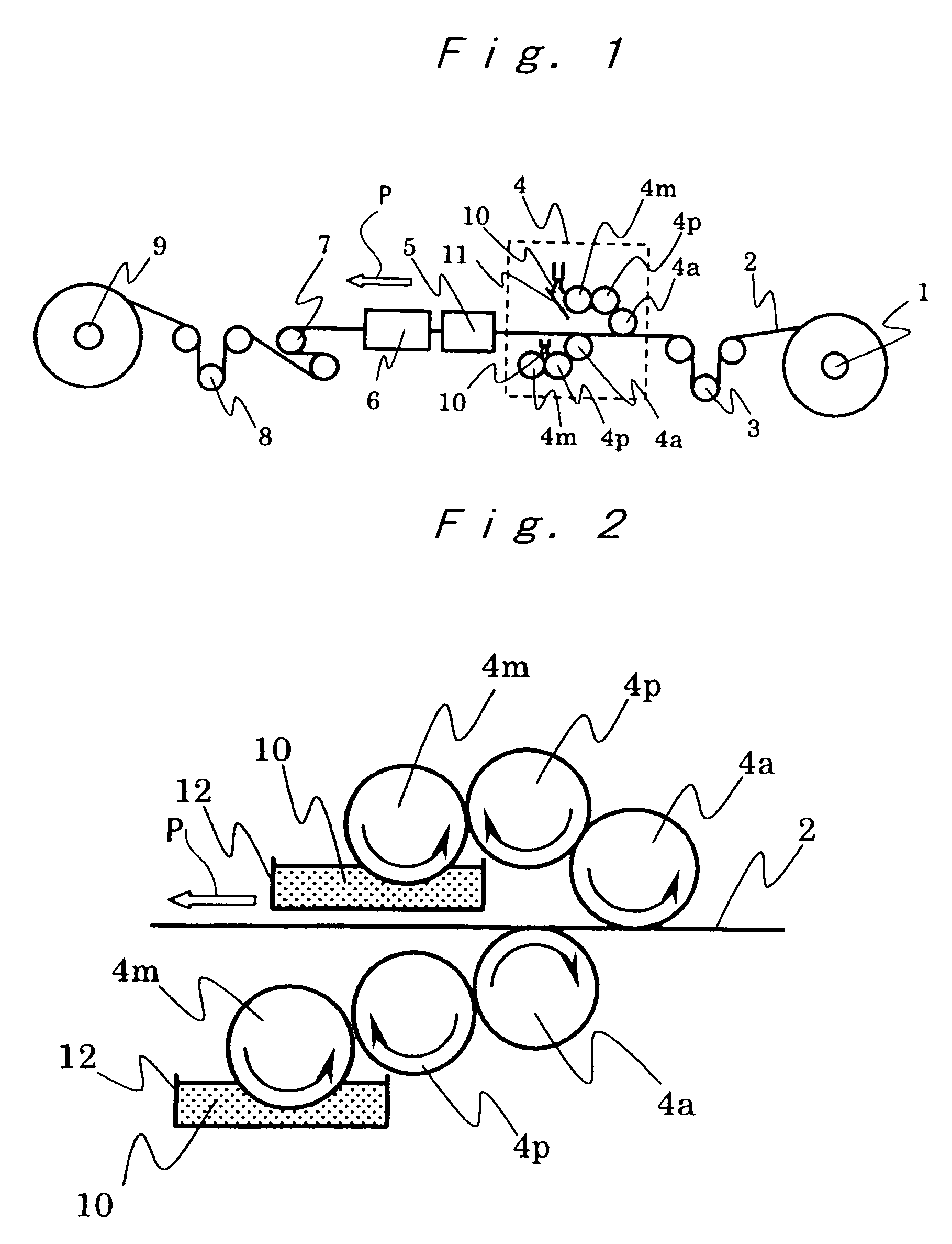
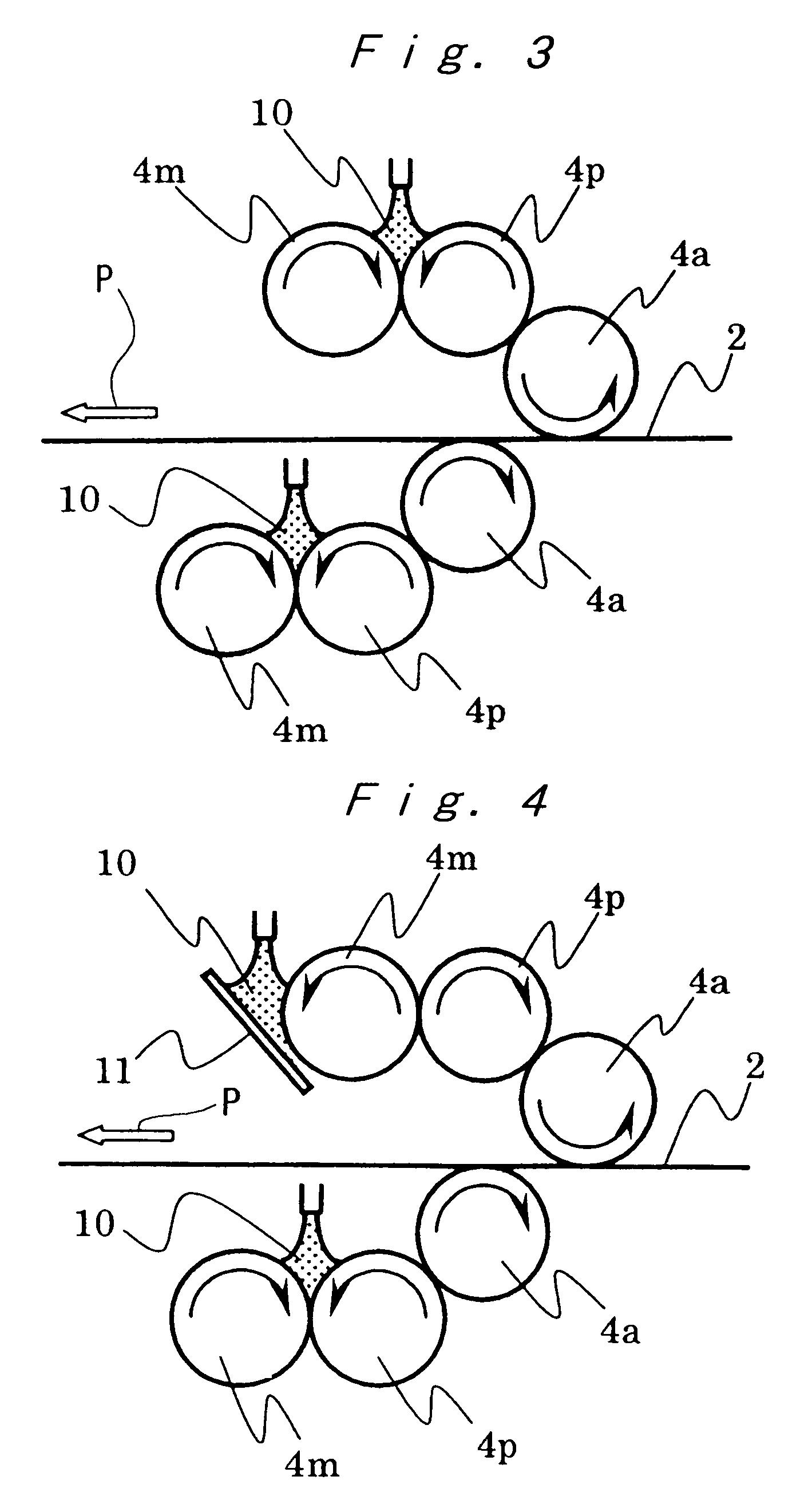
[0118]A flat multi-cavity tube 2 made of an A1050 aluminum alloy (19 cavities, 16 mm in width, 1.8 mm in high, 1.0 mm×0.6 mm in cavity size, and 0.3 mm in thickness) extruded by means of a conform extrusion method, was used; and both the top and back sides of the tube 2 was coated, with a coating apparatus as shown in FIG. 1, under the conditions of a coating chamber temperature of 25° C. The moving speed of the flat multi-cavity tube at the time of application of the coating was 80 m / min, the circumferential speed of the applicator roll 4a (200 mm in outer diameter) was 100 m / min, the circumferential speed of the pickup roll 4p (200 mm in outer diameter) was 50 m / min, and the circumferential speed of the metering roll 4m (200 mm in outer diameter) was 15 m / min. The transferring method for each roll was of the A system, as shown in FIG. 4. That is, the applicator roll 4a and the metering roll 4m were rotated in the direction opposite to the moving direction of the flat multi-cavity ...

example 1-2

[0119]Sample Nos. 5 to 8 shown in Table 1 were prepared in the same manner as in Example 1-1, except by using the system B as shown in FIG. 5, as a roll transfer system, but other conditions were the same as those of Example 1-1. The thus-prepared coated materials were subjected to the brazing process under the same conditions as those of Example 1-1. The furnace length of the induction heating furnace was 1 m for the production speed of 80 m / min (Nos. 1 to 3 and 5 to 7), or 2 m for the production speed of 160 m / min (Nos. 4 and 8).

reference example 1-1

[0121]Sample Nos. 13 to 16 were prepared in the same manner as in Example 1-1 under the conditions including the roll transfer system and the coating's characteristics, except that the hot air furnace 14 was used for the drying method as shown in FIG. 8. The temperature of an atmosphere inside the hot air furnace14 in the drying method was set to be 220° C. The reason for setting at 220° C. is as follows. A normal brazing process is inhibited as an acryl resin component is decomposed when the sample is heated at a temperature over 230° C., so the above 220° C. is the highest heating temperature within the range that does not exert any influence on the brazing process. The hot air furnaces of 1 m, 4 m, and 8 m in furnace length were used, respectively. The thus-prepared coated materials were subjected to the brazing process under the same conditions as those of Example 1-1.

[0122]The thus-applied coated layer was evaluated for coating characteristics including adhesion property, brazi...


PUM

PropertyMeasurementUnit
Raaaaaaaaaaa
Raaaaaaaaaaa
particle diameteraaaaaaaaaa

Abstract

An coating apparatus, wherein the apparatus applies a coating, onto a surface of an aluminum alloy member for a heat exchanger to be assembled by brazing, with a top-feed-type roll transfer system having at least three rolls, the coating being obtained by mixing into an organic binder a metal powder, a flux powder, a powder mixture thereof, or a compound containing a metal component and a flux component, wherein rotation directions of transfer rolls of the apparatus arranged above a surface to be coated of an aluminum alloy extruded member that moves in a horizontal direction, satisfy a relationship in which a rotation direction of a coated-metal roll for coating, which rotates in a direction opposite to a moving direction of the extruded member, and a rotation direction of a metal roll for adjusting an adhesion amount of the coating by contacting with the above roll, are opposite to each other; and a method of producing an aluminum alloy heat exchanger member using the apparatus; and an aluminum alloy heat exchanger member.

Description

[0001]This application is a continuation of international application PCT / JP2004 / 015745 filed on Oct. 18, 2004.TECHNICAL FIELD[0002]The present invention relates to a method of producing an aluminum alloy member for a heat exchanger, which can be assembled by means of a brazing process. The present invention also relates to an apparatus using the above method. The present invention also relates to an aluminum alloy heat exchanger member, on which a filler material is applied with the above apparatus or method.[0003]Further, the present invention relates to a material composed of an aluminum alloy, for example, an aluminum alloy flat multi-cavity tube coated with a coating containing metal powder for brazing an aluminum material, which is used for brazing the aluminum material. Further, more specifically, the present invention relates to a resin-coated aluminum alloy flat multi-cavity tube for a heat exchanger, which is coated with a coating containing metal powder suitable for brazi...

Claims


Application Information

Patent Timeline
Patent Type & Authority Patents(United States)
IPC IPC(8): B05D3/00B05D5/00B05D3/06B22F1/107
CPCB22F7/04B23K1/20C23C24/06C23C24/10C23C26/00C23C26/02F28F1/022F28F21/084F28F21/089B23K2101/14B23K2103/10B22F1/107C23C2/00344C23C2/0035
Inventor YAMAGUCHI, HIROKAZUMAEZONO, TOSHIKIKASHIMA, TAKASHIKOJIMA, MASAMIHIRANO, YOJI
Owner FURUKAWA SKY ALUMINUM CORP
Why Eureka
Try Eureka